36 HyPrecision 50S/60S/75S Operator Manual 808690
2 – Product description
Product description
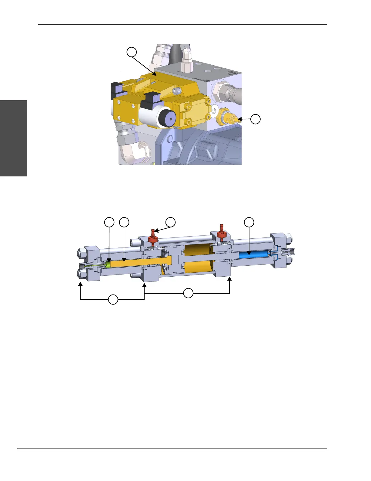
Primary hydraulic manifold
A shift valve mounted on the manifold directs the flow of pressurized hydraulic fluid to alternating sides of the
intensifier. A relief valve protects the pump from too much pressure.
Intensifier
A proximity switch at each end of the hydraulic center section signals the shift valve.
Ceramic plungers connected to each side of the piston extend into the left and right high-pressure ends.
Hydraulic fluid pushes the piston to 1 side while low-pressure supply water fills the empty cylinder. The plunger
on the opposite side of the cylinder compresses the water for piercing or cutting.
1 Shift valve 2 Relief valve
1 High-pressure water
2 Plunger
3 Proximity switch
4 Low-pressure water
5 High-pressure end
6 Hydraulic center section