4
MAINTENANCE
powermax1250 Service Manual 3-41
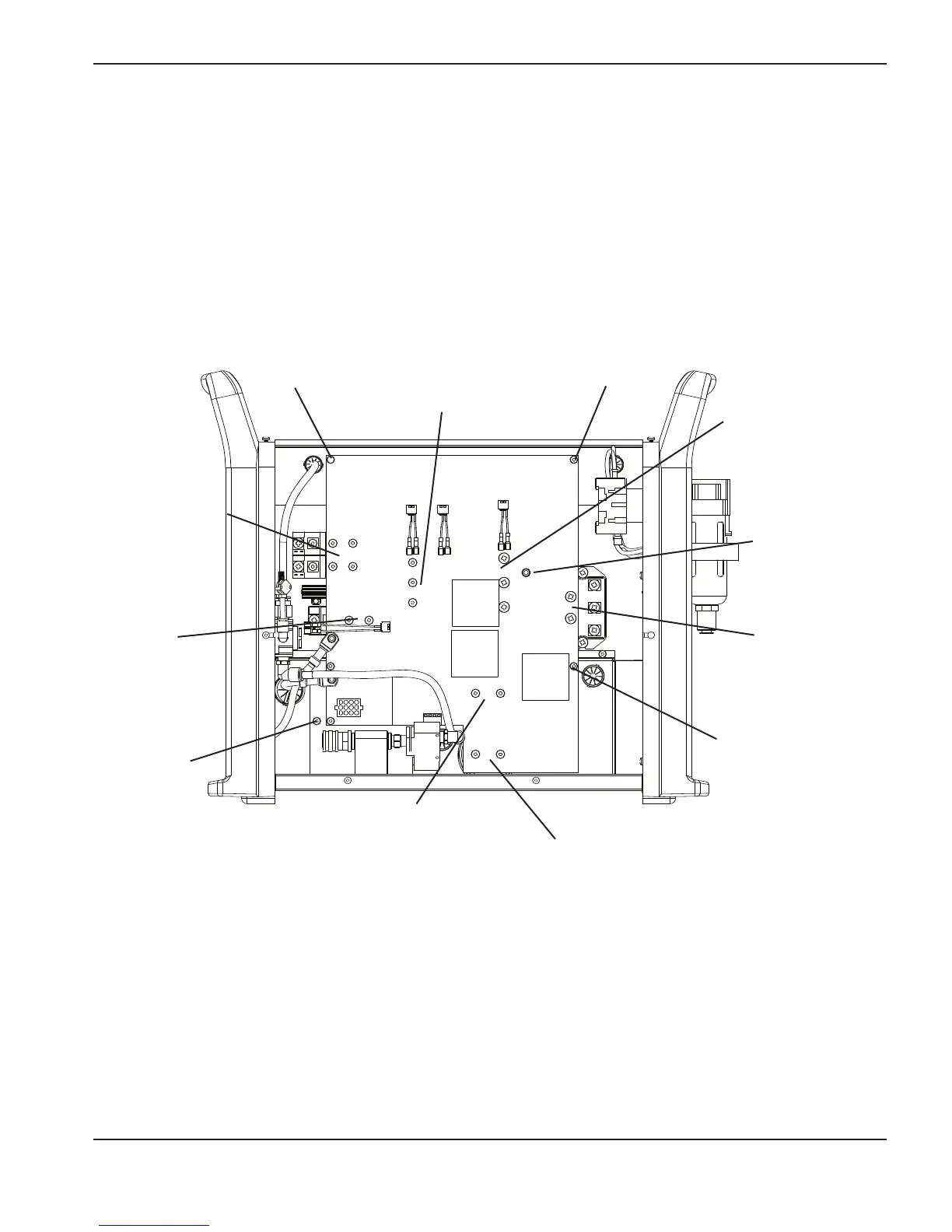
Retaining
screw
Retaining
screw
Retaining
screw
Retaining
screw
PFC IGBT screws (3),
black cable attached
with the bottom screw
(J17)
Input diode bridge
screws (2), black
wire attached with
the bottom screw
Output diode
bridge screws (4),
black cable
attached with the
bottom left screw
and the black wire
attached with the
top left screw.
Inverter IGBT screws
(3), yellow cable
attached with the
bottom screw
Pilot arc IGBT
screws (2)
Capacitor (C94)
screws (2)
Capacitor (C98) screws (2),
yellow cable and black wire
attached with the left screw
Current sensor
cable (J9)
7.
Remove the screws that secure the power board to the capacitors, the input diode bridge, and the IGBTs.
Remove any cables connected at those points. Then remove the retaining screws from the power board.
8. Lift the power board out of the power supply and store it in an anti-static container until you are ready to
re-install it.
6. Disconnect the pin connectors and cables attached to the board at:
• J1, J2 and J3
•J5
• The ribbon cable at J14
•
The current sensor cable at J9
• J11 and J13
• J20 and J21
 Loading...


