4
MAINTENANCE
3-42 powermax1250 Service Manual
Installation
1. Seat the power board into the base of the power supply. Then replace the retaining screws that hold the power
board in place.
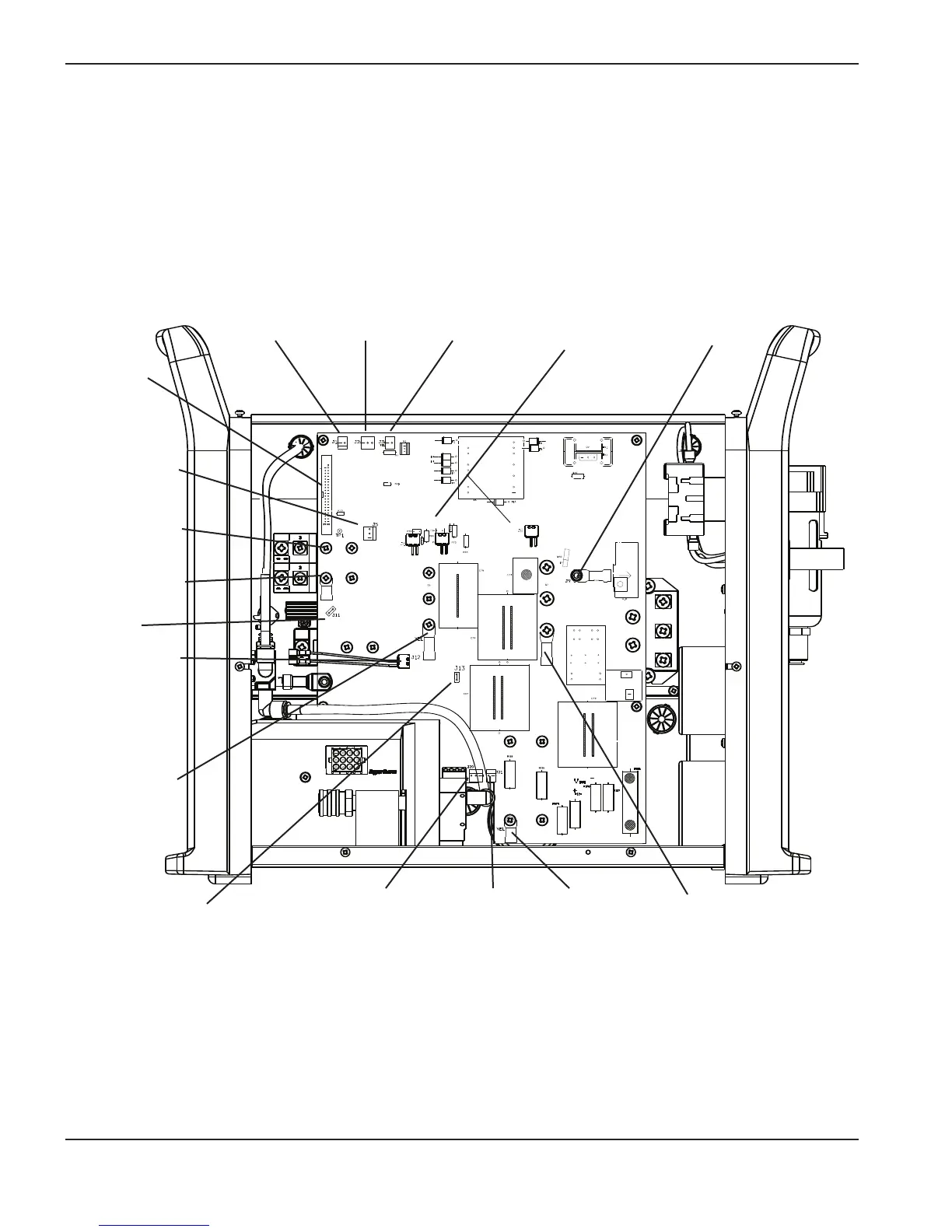
2. Attach all gate drives, cables, IGBT and capacitor screws, wires and input and output diode screws.
Note: The required torque for each of these screws is 20 in-lb (24 kg cm).
J1, 2-pin,
red/black
J2, 3-pin,
yellow/black
J3, 2-pin,
yellow/black
J5 3-pin,
red/yellow/black
Ribbon
cable
Black wire
Black cable
Pilot arc gate
drive (J12)
J20, 3-pin,
red/black
J21, 2-pin,
red/black
Yellow cable
and black wire
Y
ellow cable
Black cable
Current sensor
cable (J9)
IGBT gate drives
(J6, J7 and J8)
J13, black wire
through the hole
in the board
J11
3. Reattach the work lead, and power cord ground cable.
4. Re-install the ETR barrier and reconnect the torch lead.
5. Replace the insulation panel and the cover on the power supply.
6. Reconnect the gas supply and the electrical power.
 Loading...


