OPERATION
3
powermax1650 Operator Manual 4-19
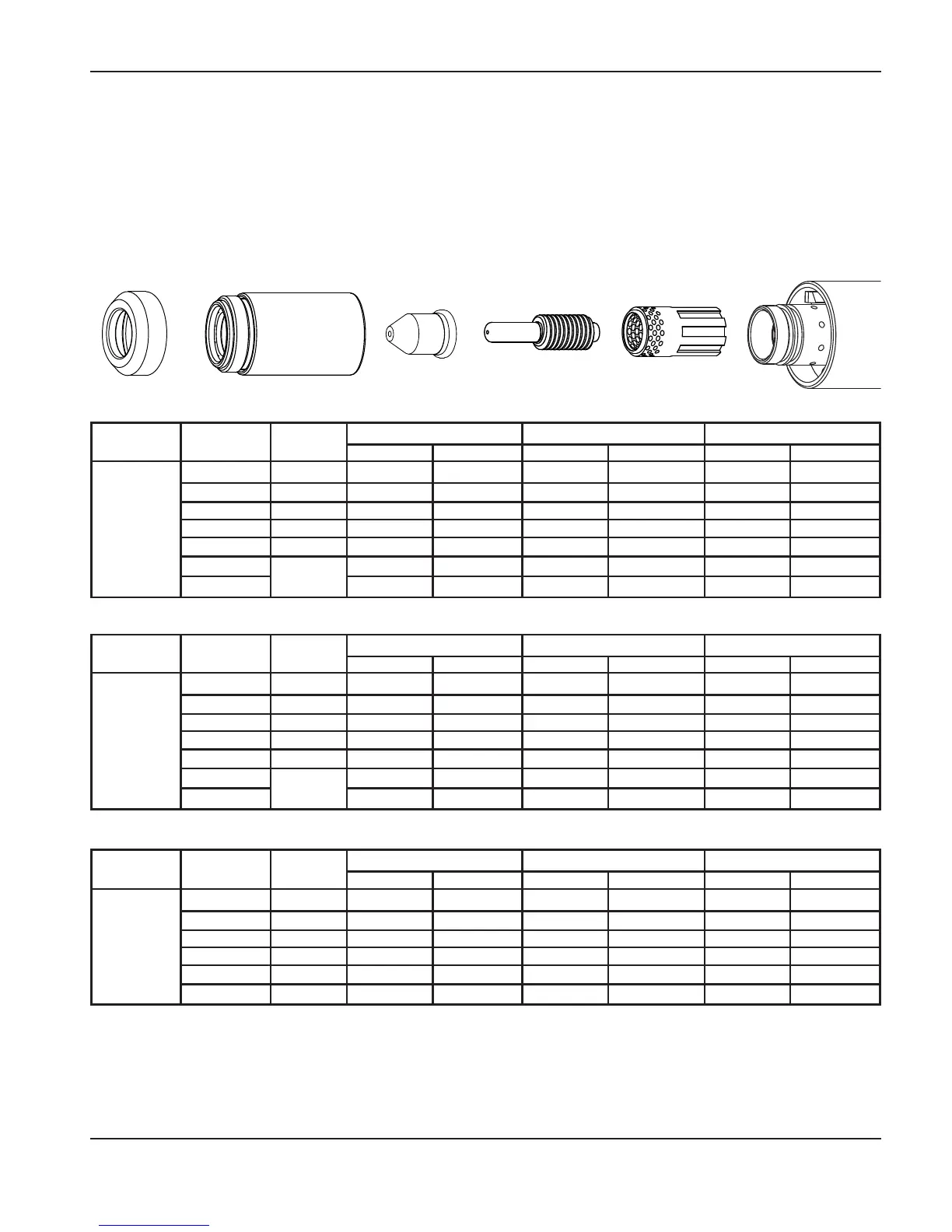
100 amp mechanized unshielded consumables
• Torch-to-work dis tance for the following cut chart is 3/16 in (4.8 mm) for all cuts.
Retaining cap
220048
Nozzle
220064
Electrode
220037
Swirl ring
220051
T100M-2
torch
Deflector
120979
Maximum travel speeds are the fastest speeds possible for cutting the material without regard to cut quality. Optimum travel
speeds provide the best cut angle, least dross and best cut surface finish. Remember that cut charts are intended to
provide a good starting point for each different cut assignment. Every cutting system requires “fine tuning” for each
cutting application in order to obtain the desired cut quality.
Arc current Arc voltage
Pierce
delay
Material thickness
Maximum travel speed Optimum travel speed
Inches mm
IPM mm/min IPM mm/min
100
136 0.5
1/4” 6.4
210 5334 137 3479
139 0.5
3/8” 9.5
122 3098 79 2006
142 1.0
1/2” 12.7
91 2311 59 1498
146 1.0
5/8” 15.9
57 1447 37 939
150 1.5
3/4” 19.0
43 1092 28 711
155
NA
1” 25.4
26 660 17 431
160
1 1/4” 31.8
16 406 10 254
Arc current Arc voltage
Pierce
delay
Material thickness
Maximum travel speed Optimum travel speed
Inches mm
IPM mm/min IPM mm/min
100
137 0.5
1/4” 6.4
255 6477 166 4216
139 0.5
3/8” 9.5
153 3886 99 2514
142 1.0
1/2” 12.7
107 2717 70 1778
147 1.0
5/8” 15.9
77 1955 50 1270
150 1.5
3/4” 19.0
51 1295 33 838
154 NA
1” 25.4
31 787 20 508
Mild steel
Stainless steel
Aluminum
Arc current Arc voltage
Pierce
delay
Material thickness
Maximum travel speed Optimum travel speed
Inches mm
IPM mm/min IPM mm/min
100
136 0.5
1/4” 6.4
241 6121 157 3987
139 0.5
3/8” 9.5
131 3327 85 2159
142 1.0
1/2” 12.7
81 2057 53 1346
146 1.0
5/8” 15.9
51 1295 33 838
150 1.5
3/4” 19.0
33 838 22 558
155
NA
1” 25.4
22 558 14 355
161
1 1/4” 31.8
11 279 7 177