EasyManuals Logo
Home>Hypertherm>Welding System>powermax1650

Hypertherm powermax1650 User Manual

Hypertherm powermax1650
106 pages
To Next Page IconTo Next Page
To Previous Page IconTo Previous Page
Page #103 background imageLoading...
Page #103 background image
M1
Cap Switch
Start Switch
~
~
-
+
Board
Power
PCB2
S1
TS1
PCB1
EMI Filter
Board
(CE Only)
Bridge
Input
D1
Diode
Regulator
Filter
Air/Gas
Source
Air/Gas
to
Torch
PCB3 Control Board
Transfer
Sensor
Nozzle
Work
IGBT
PA
Q3
xfmr
Power
T2
D2
Output
Diode
Bridge
J1
~
~
-
+
Workpiece
Electrode
Torch
Q2
Invertor
IGBT
L1
L2
TS2 TS3
PS1
Pressure
Sensor (gas)
V1
Solenoid
Valve (gas)
IFB
~
AC Input
PE
Q1
Boost
IGBT
7050STATUS
GAS
45 6055 65 75 80 85
CPA
NORMAL
GOUGE
CURRENT
DOWN
MID
UP
AC
V
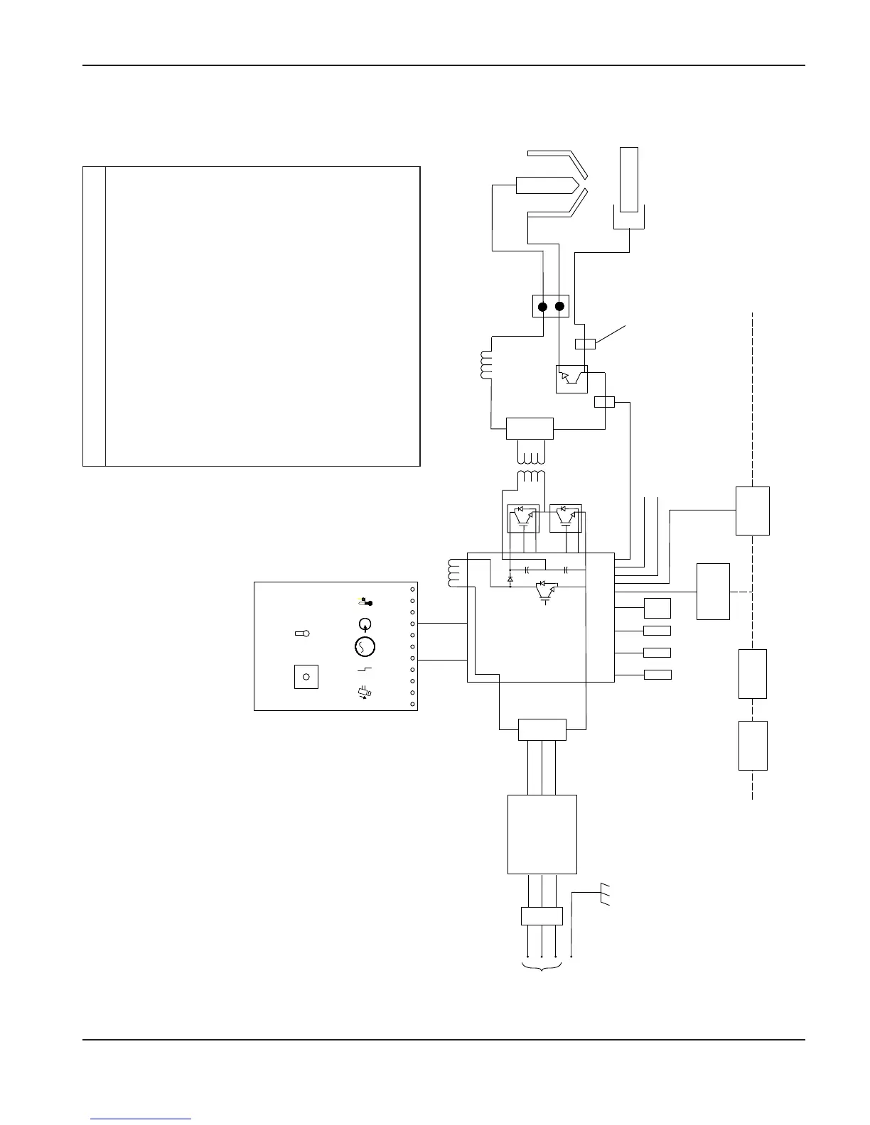
System circuit diagram
Designator Component
D1 .......................Input diode bridge
D2 .......................Output diode bridge
L1 ........................Boost inductor
L2 ........................Output inductor
M1.......................Fan
PCB1 .................EMI filter board
PCB2 .................Power board
PCB3 .................Control board
PS1.....................Pressure sensor
Q1.......................Boost IGBT
Q2.......................Inverter IGBT
Q3.......................Pilot arc IGBT
S1........................On/off switch
J1.........................Connector
TS1,TS2.............Heatsink temperature sensor
TS3 .....................Transformer temperature sensor
T2........................Power transformer
V1........................Solenoid valve
powermax1650 Operator Manual 5-9
0
MAINTENANCE AND PARTS

Table of Contents

Other manuals for Hypertherm powermax1650

Questions and Answers:

Question and Answer IconNeed help?

Do you have a question about the Hypertherm powermax1650 and is the answer not in the manual?

Hypertherm powermax1650 Specifications

General IconGeneral
BrandHypertherm
Modelpowermax1650
CategoryWelding System
LanguageEnglish

Related product manuals