Bleed the System 5000 SRM 969
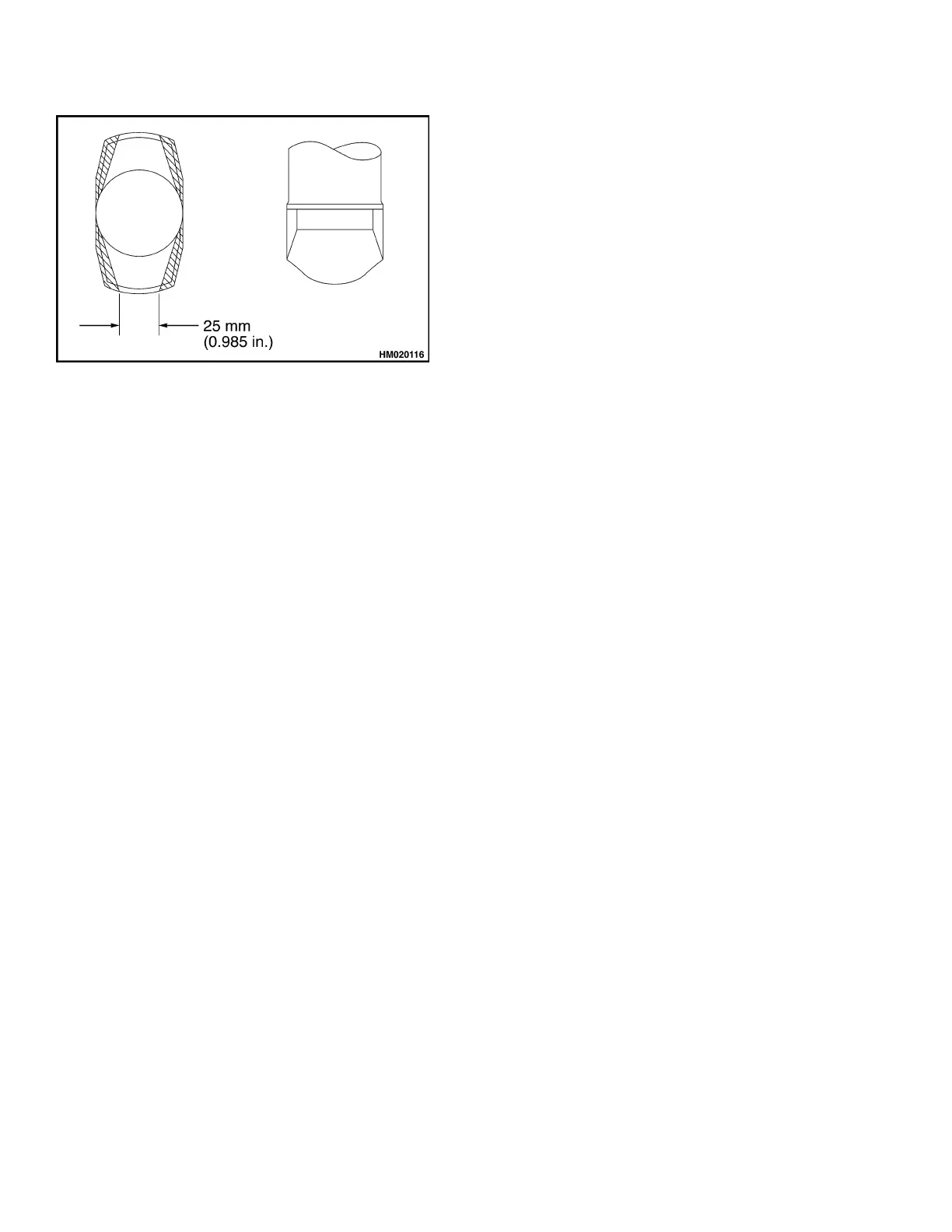
Figure 11. Twist Lock Wear
2. Inspectupperandlowerbearingsetsfordamage.
Replace if damaged or worn. Bearings are con-
sidered worn and in need of replacement, if axial
play of twist lock is more than 3 mm (0.118 in.).
ASSEMBLE
1. Lubricate upper and lower bearings using multi-
purposegrease.SeeFigure4.
2. Install sleeve (35) with bushings (19) onto twist
lock and position lower bearing (18) on top of
sleeve. Install four centering springs in sides of
sleeve.
3. Install upper bearing (17) on top surface of frame
plate with threaded holes facing up.
4. Install twist lock through frame plate in end
beam ensuring that upper bearing set is cor-
rectly positioned around twist lock. Support the
assembly by means of a jack or other suitable
device to make sure assembly does not fall out.
5. Install collets with sloping side facing up.
6. Install key and roll pin in keyway of twist lock.
NOTE: To ease in installation of crank to twist lock,
make two alignment pins using M8×75 bolts or
socket head screws with heads removed.
7. Install alignment pins into top plate of upper
bearing diagonally so each pin guides on half of
collets.
8. Insert tie rod end (28) and fit crank onto align-
ment pins making sure key and keyway are lined
up.
9. Install two bolts (15) in crank, remove alignment
pins, and install remaining two bolts in crank.
Tighten all four bolts to 25 N•m (18.44 lbf).
10. Install lockwasher (4), socket head screw (3), ring
pin (2), and holding pin (14).
11. Install rod (10).
12. Install cover (43).
13. Adjust twist lock angle and proximity switches.
See Twist Lock Angle Adjustment.
14. Lubricate complete assembly using multipur-
pose grease.
Bleed the System
1. Loosen hose at cylinder or hydraulic motor and
operate related function until oil comes out of
connection.
2. Retighten hose.
3. Loosen hose for same function at opposite end
and operate related function until oil comes out
of connection.
4. Repeat procedure at least once.
18