5000 SRM 969 Maintenance
INTERFACE BOXES
Model 555
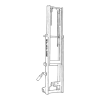
NOTE: Box is on left side, positioned on extension cylinder. See Figure 21.
LED No.
Interface
Box
Function Indication Status
Green SpB5 Indicates +24V supply voltage present ON When Present
Yellow
3
SpB5 Indicates command extend LH present ON When Present
Yellow
4
SpB5 Indicates command retract LH present ON When Present
NOTE: Box is on right side, positioned on extension cylinder.
LED No.
Interface
Box
Function Indication Status
Green SpB6 Indicates +24V supply voltage present ON When Present
Yellow
3
SpB6 Indicates command extend RH present ON When Present
Yellow
4
SpB6 Indicates command retract RH present ON When Present
NOTE: Box is on sideshift cylinder, positioned on carriage.
LED No.
Interface
Box
Function Indication Status
Green SpB8 Indicates +24V supply voltage present ON When Present
Yellow
1
SpB8 Indicates command sideshift LH present On When Present
Yellow
2
SpB8 Indicates command sideshift RH present ON When Present
Models 553 and 558
NOTE: Box is on left side, positioned on extension cylinder.
LED No.
Interface
Box
Function Indication Status
Green SpB5 Indicates +24V supply voltage present ON When Present
Yellow
1
SpB5 Indicates command lock twist lock LH
present
ON When Present
Yellow
2
SpB5 Indicates command unlock twist lock LH
present
ON When Present
Yellow
3
SpB5 Indicates command extend LH present ON When Present
Yellow
4
SpB5 Indicates command retract LH present ON When Present
NOTE: Box is on right side, positioned on extension cylinder.
25