5000 SRM 969 Adjustments
2. Adjust space between sensor and ring to 1 mm
(0.039 in.) using a feeler gauge.
3. Tighten four bolts holding sensors.
Model 558
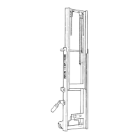
1. Check twist lock angle. See Figure 4.
2. Put twist lock in LOCKED position.
3. Loosen nylon mounting sensor bracket (6).
4. Slide LOCKED sensor toward flag (32) until it
switches ON, then an additional 3 mm (0.118 in.).
5. Tighten sensor bracket (6).
6. Turn twist locks to NOT-LOCKED position
7. Loosen sensor bracket (6).
8. Slide NOT-LOCKED sensor toward flag (32)
until it switches ON, then an additional 3 mm
(0.118 in.).
9. Replace sensors if they do not switch ON at a
distance equal or larger than 4 mm (0.157 in.).
NOTE: There is some play in movement of twist locks.
10. Check that play in movement of twist lock does
not cause a sensor to switch ON or OFF. Verify
both end positions by twisting twist lock back
and forth.
SEATED SENSOR ADJUSTMENT
Model 553
NOTE: The lenses on front side of sensors will give
inaccurate readings if they are dirty or oily. Clean
lens with a clean, soft wipe prior to adjusting sensor.
NOTE: When distance between housing and con-
tainer is set at 25 mm (0.984 in.), there are 12 mm
(0.47 in.) of play between the twist lock and inside
contact of container pocket.
1. The SEATED sensor should indicate seated. The
amber light on the attachment and LED on con-
trol box should be ON when distance between
twist lock housing and container is 25 to 30 mm
(0.984 to 1.181 in.).
2. To make adjustments, remove end beam cover.
The top hole provides access to adjustment screw
of SEATED sensor.
3. Turn adjustment screw clockwise to increase dis-
tance.
4. Turn adjustment screw counterclockwise to de-
crease distance.
Model 558
1. Check that seated pin (21) can move up and down
easily. The force needed to lift a pin is approxi-
mately 100 N (22.5 lbf). See Figure 4.
2. Loosen two bolts (27) and remove bracket (9) and
sensor (8).
3. Loosen clamp bolts holding sensor and replace
sensor if required.
4. Position sensor such that distance between sen-
sor face and bracket mounting surface is 7.9 to
8.1 mm (0.311 to 0.319 in.).
5. Tighten clamp bolts.
6. Mount clamp with sensor using two bolts (27).
7. Slowly move seated pin (21) upward until seated
sensor switches ON.
8. Measure distance between bottom end of seated
pin (21) and head (26). The distance should be 9
to 10 mm (0.354 to 0.394 in.).
9. Reposition seated sensor higher if distance is
more than 10 mm (0.394 in.) and lower if dis-
tanceislessthan9mm(0.354in.).
OVERLOWERING PROTECTION SENSOR
ADJUSTMENT (MODELS 553 AND 558)
1. Place end beams in lowered position.
2. Loosen bolts of sensor bracket.
3. Slide sensor toward activating plate until it
switches ON.
4. Move sensor 2 mm (0.08 in.) farther toward plate
and tighten bolts of sensor bracket.
5. Replace sensor if it has not switched ON at a dis-
tance of 4 mm (0.16 in.) from plate.
21