Adjustments 5000 SRM 969
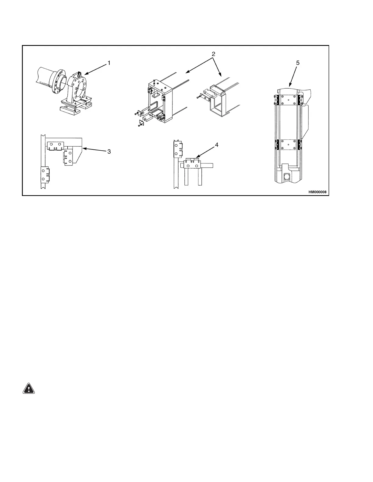
1. EXTENSION CYLINDER SUPPORT
2. MAIN FRAME AND EXTENSION BEAM
3. UPPER SIDESHIFT SLIDE PADS
4. LOWER SIDESHIFT SLIDE PADS
5. END BEAM SLIDE PADS
Figure 13. Slide Pads
Adjustments
TWIST LOCK ANGLE ADJUSTMENT
Model 558 Only
1. Disconnect rod (10) from flag indicator (12). See
Figure 4.
2. Remove socket head screw and washer (49), and
disconnect rod (10) from pin (14).
3. Remove ring pin (2), socket head screw (3), and
lockwasher (4). Remove pin (14).
4. Put piston of the twist lock cylinder in fully NOT-
LOCKED position.
5. Put twist lock in fully NOT-LOCKED position.
WARNING
Twist locks can get caught in corner casting of
container if twist locks have not been aligned
and adjusted properly.
6. Loosen bolts (29) at tie rod end (28) and adjust
to required length by turning rod end on cylinder
assembly (11). Tighten bolts (29).
7. Insert pin (14).
8. Install lockwasher (4), socket head screw (3), and
ring pin (2) holding tie rod end (28) on crank.
9. Install rod (10) onto flag indicator (12) and onto
pin (14) using socket head screw and washer (49).
NOTE: After NOT-LOCKED position has been cor-
rectly set, piston range of twist lock cylinder ensures
a correct LOCKED position.
LOCKED/NOT LOCKED SENSORS
ADJUSTMENT
Model 553
1. Loosen bolts holding LOCKED and NOT
LOCKED sensors.
20