Maintenance 5000 SRM 969
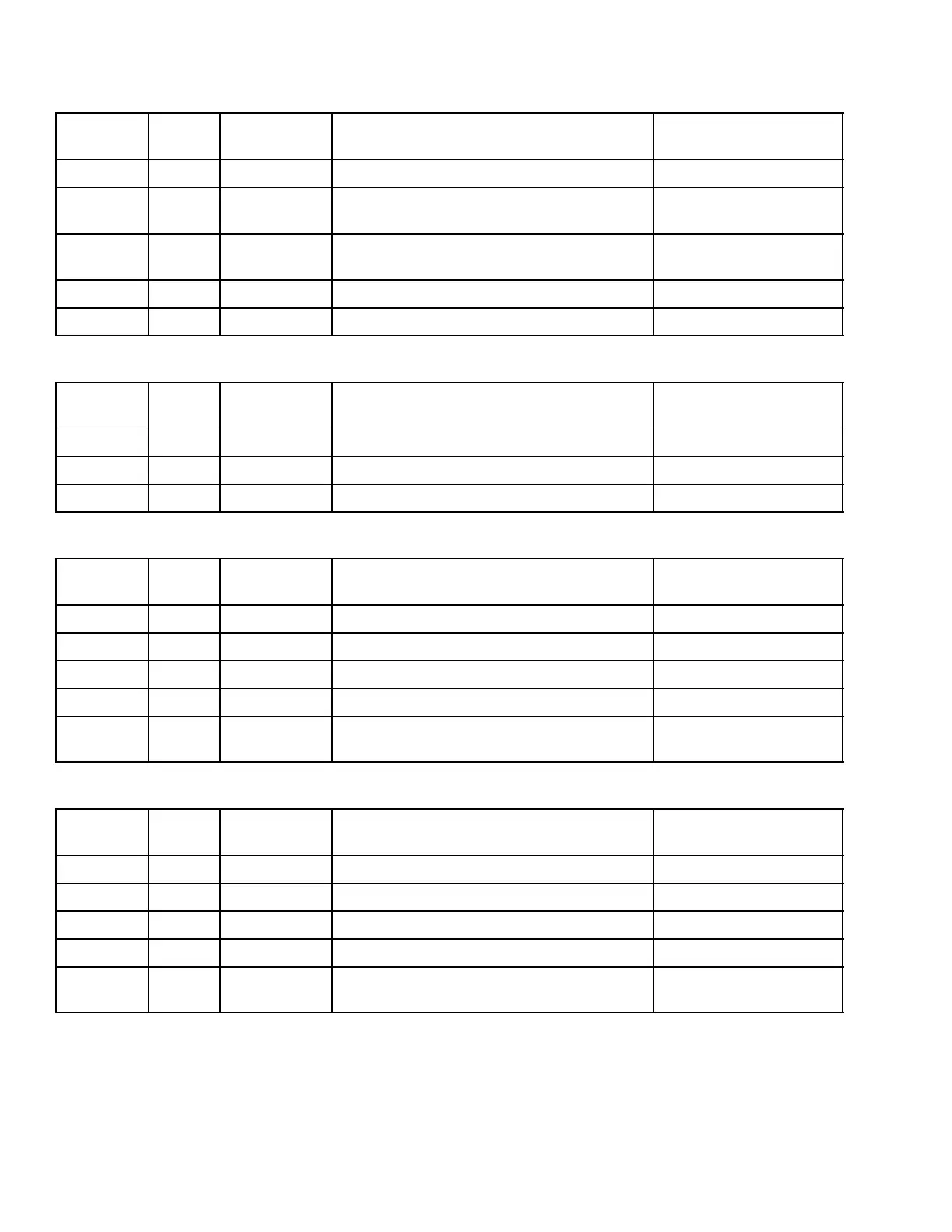
LED No.
Interface
Box
Function Indication Status
Green SpB6 Indicates +24V supply voltage present ON When Present
Yellow
1
SpB6 Indicates command lock twist lock RH
present
ON When Present
Yellow
2
SpB6 Indicates command unlock twist lock RH
present
ON When Present
Yellow
3
SpB6 Indicates command extend RH present ON When Present
Yellow
4
SpB6 Indicates command retract RH present ON When Present
NOT
E: Box is near sideshift cylinder, positioned on carriage.
LED No.
Interface
Box
Function Indication Status
Green SpB8 Indicates +24V supply voltage present ON When Present
Yellow
1
SpB8 Indicates command sideshift LH present ON When Present
Yellow
2
SpB8 Indicates command sideshift RH present ON When Present
NOTE: Box is near LH twist lock head, positioned on vertical end beam cylinder.
LED No.
Interface
Box
Function Indication Status
Green SpB3 Indicates +24V supply voltage present ON When Present
Yellow
1
SpB3 Indicates LH twist lock is locked ON When Present
Yellow
2
SpB3 Indicates LH twist lock is unlocked ON When Present
Yellow
3
SpB3 Indicates LH twist lock is seated ON When Present
Yellow
4
SpB3 Indicates overlowering interrupt not
activated
On When Not Activated
NOTE: Box is near RH twist lock head, positioned on vertical end beam cylinder.
LED No.
Interface
Box
Function Indication Status
Green SpB4 Indicates +24V supply voltage present ON When Present
Yellow
1
SpB4 Indicates RH twist lock is locked ON When Present
Yellow
2
SpB4 Indicates RH twist lock in unlocked ON When Present
Yellow
3
SpB4 Indicates RH twist lock is seated ON When Present
Yellow
4
SpB4 Indicates overlowering interrupt not
activated
ON When Present
26