5. Appendix
276
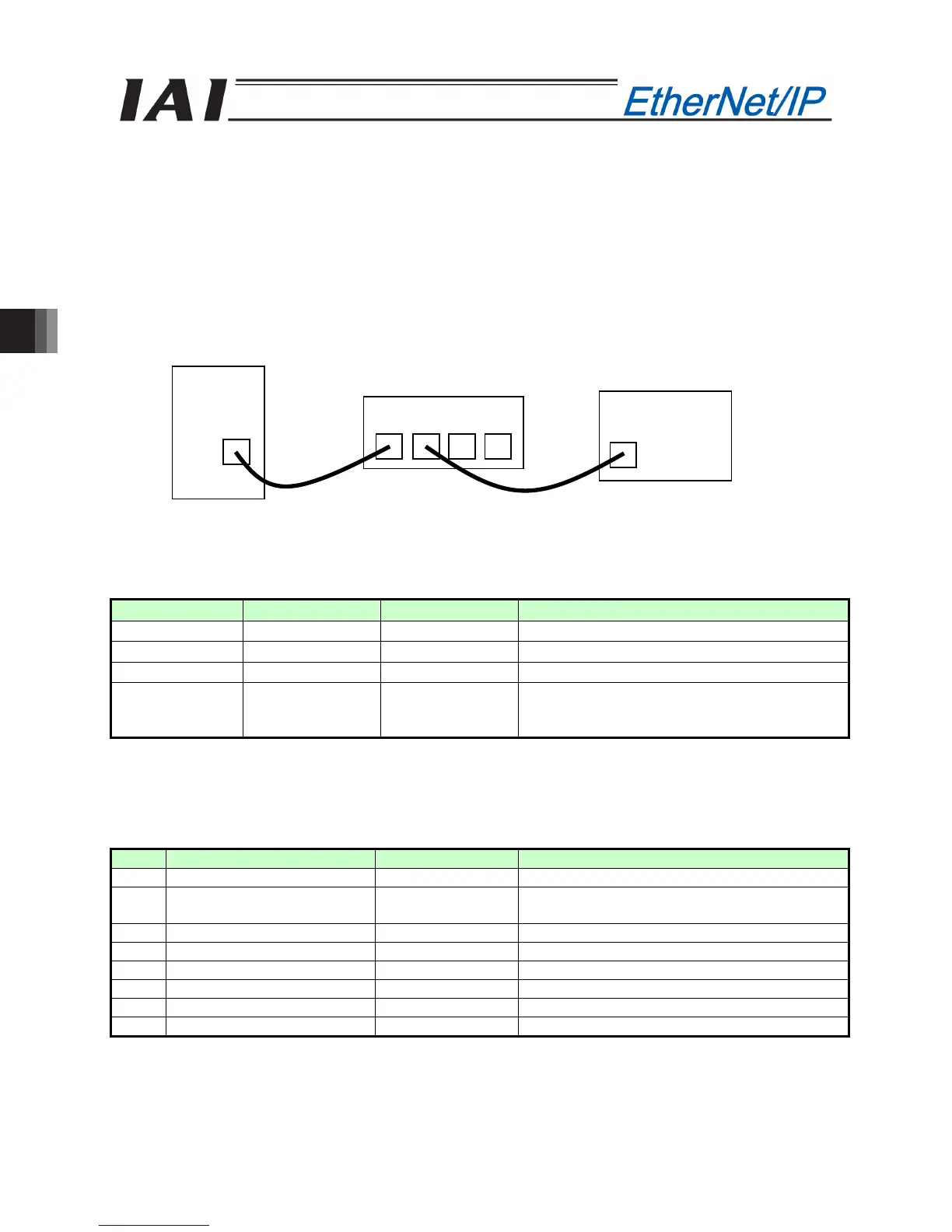
PLC
IAI RC
controller
Switching hub
LAN cable
LAN cable
5.2 Example of Connection Settings with Keyence’s Master
The following devices and software are needed to connect to Keyence’s master:
[1] PLC CPU unit: (Example) KV-5500 (with built-in EtherNet/IP)
[2] Configuration software: (Example) KV-STUDIO Ver 6.10 or later
[3] Commercially available switching hub (supporting 100BASE-TX)
[4] IAI controller of EtherNet/IP specification
[5] Straight LAN cable (category 5, 5e or larger) x 2 pcs
5.2.1 Connection Example
A setting example based on the following connection configuration is given.
(Note) The power supply, actuator, etc., are not illustrated.
The connection procedure explained on the following pages is based on the following settings:
Item Controller PLC Remarks
IP address 192.168.0.1 192.168.9.10
Subnet mask 255.255.255.0 255.255.255.0
Default gateway 0.0.0.0 0.0.0.0 Disable the default gateway.
Baud rate Set automatically. Set automatically.
100 Mbps/full-duplex when link is established
(The specific settings vary depending on the
switching hub specification.)
5.2.2 Setting the Controller
Actuate an emergency stop on the controller and then start the controller with the MODE switch set to
MANU. (This is to prevent the motor from starting due to output signals from the PLC.)
Start the RC PC software and set the user parameters for the controller.
(Keep all parameters at their factory settings.)
No. Name Set value Remarks
25 PIO pattern selection 0 Standard mode
84 Fieldbus operation mode 0
Remote I/O mode
(I/O sizes: 2 bytes/2 bytes)
86 Fieldbus baud rate 0 Automatically negotiated.
87 Network type 7 EtherNet/IP
90 Fieldbus I/O format 3 Byte swap/word swap
140 IP address 192.168.0.1
141 Subnet mask 255.255.255.0
142 Default gateway 0.0.0.0 Disable the default gateway.

 Loading...


