3. SCON-CA/CFA
93
3.6 Communicating with the Master Station
3.6.1 Operation Modes and Corresponding PLC I/O Areas
The addresses allocated for each operation mode are described as follows.
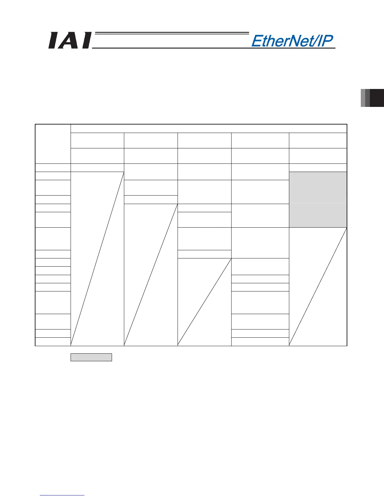
x PLC output o PCON-CA/CFA input (* “n” indicates the first output address of each axis.)
DI on the PCON-CA/CFA side and input data register
Remote I/O mode
Position/simplified
direct value mode
Half direct value
mode
Full direct value
mode
Remote I/O mode 2
PLC output
area (bytes)
Number of
occupied bytes: 2
Number of
occupied bytes: 8
Number of
occupied bytes: 16
Number of
occupied bytes: 32
Number of
occupied bytes: 12
n, n+1 Port No.0 to 15 Port No.0 to 15
n+2, n+3
Target position Target position Target position
n+4, n+5
Specified position
number
n+6, n+7 Control signal
Positioning band Positioning band
n+8, n+9 Speed
n+10, n+11
Acceleration/
deceleration
Speed setup
Occupied area
n+12, n+13
Pressing
current-limiting
value
n+14, n+15 Control signal
Zone boundary+
n+16, n+17
n+18, n+19
Zone boundary-
n+20, n+21 Acceleration
n+22, n+23 Deceleration
n+24, n+25
Pressing
current-limiting
value
n+26, n+27
Load current
threshold
n+28, n+29 Control signal 1
n+30, n+31 Control signal 2
(Note) The Occupied area shows the area to be occupied with the operation mode setting.
Therefore, this area cannot be used for any other purpose. Also, exercise caution to avoid node address
duplication.

 Loading...


