4. SCON-CA
217
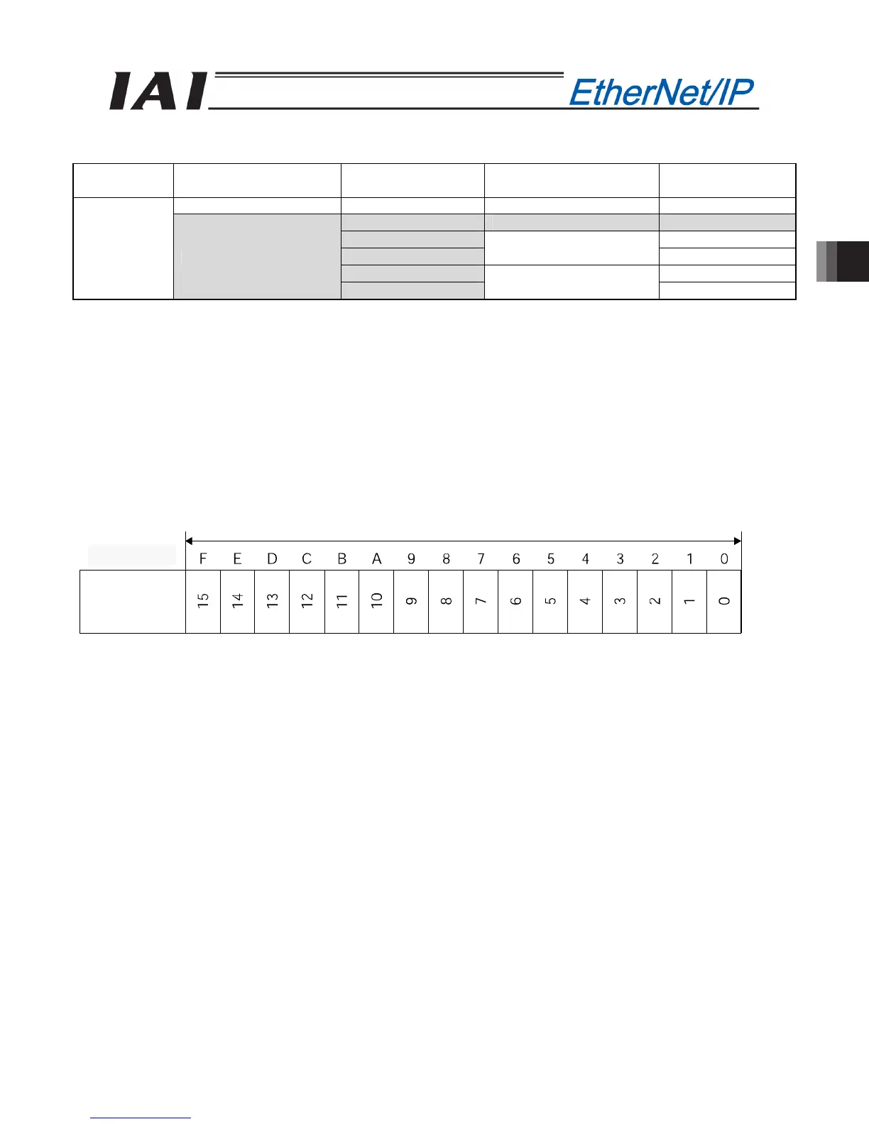
(1) PLC address configuration (* “n” indicates the node address of each axis.)
Parameter
No. 84
SCON-CA side
DI and input register
PLC side output
address (bytes)
SCON-CA side
DO and output register
PLC side input
address (bytes)
Port number 0 to 15 n+0, n+1 Port number 0 to 15 n+0, n+1
n+2, n+3 Occupied area n+2, n+3
n+4, n+5 n+4, n+5
n+6, n+7
Current position
n+6, n+7
n+8, n+9 n+8, n+9
7
Occupied area
n+10, n+11
Force feedback data
n+10, n+11
(Note) The areas denoted by Occupied area cannot be used for any other purpose.
Also, exercise caution to avoid node address duplication.
(2) I/O Signal Allocation for each Axis
The I/O signals of each axis consist of one input word (6 words = 12 bytes) and one output word in the I/O
areas.
z The areas controlled by port number are controlled using ON/OFF bit signals.
z The current position is a 2-word (32-bit) binary data (unit: 0.01 mm).
z The force feedback data is a 2-word (32-bit) binary data (unit: 0.01N).
PLC output
Address (* “n” indicates the node address of each axis.)
1 word = 2 bytes =16 bits
n+0ޔn+1
Controller
input port
number
n+0, n+1

 Loading...


