AFE1_AFE2-1:1
24
Technical specifications
IAR Debug Probes User Guide
I-jet®, I-jet Trace, and I-scope™
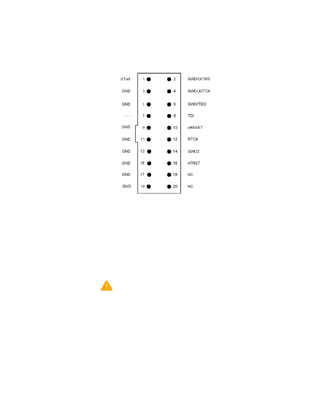
MIPI20 connector pinout on target side
For more information about the signal descriptions, see The JTAG/SWD - MIPI-20
cable, page 16.
Important safety and disclaimer note
The continuous normal operation voltage across the isolation barrier should not exceed
300 V DC.
The isolation voltage only represents a measure of immunity to transient voltages—the
probe should never be used as an element of a safety isolation system. For use with
higher continuous voltages, additional isolation/insulation systems must be used in
accordance with the safety standard requirements.
When handling equipment subjected to high voltages, use caution and follow all safety
regulations. Touching any exposed circuitry on the target, the adapter, cables, or the I-jet
probe can cause injury or death.
IAR Systems or the manufacturer shall not be liable for any damages related to the use
of this probe.