INSTALLATIONS
18
IB895 User’s Manual
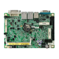
JP1: Front Panel Connector
The following table shows the pin outs of the 2x4 pin header
Signal Name Pin # Pin # Signal Name
Ground 1 2 PWR_SW
PWR_LED+ 3 4 PWR_LED-(GND
)
HDD_LED+ 5 6 HDD_LED-
Ground 7 8 RESET
JP1 provides connectors for system indicators that provide light
indication of the computer activities and switches to change the
computer status. JP1 is an 8-pin header that provides interfaces for the
following functions.
ATX Power ON Switch: Pins 1 and 2
This 2-pin connector is an “ATX Power Supply On/Off
Switch” on the system that connects to the power switch on
the case. When pressed, the power switch will force the
system to power on. When pressed again, it will force the
system to power off.
Power LED: Pins 3 and 4
Pin # Signal Name
3 LED(+)
4 LED(-)
Hard Disk Drive LED Connector: Pins 5 and 6
This connector connects to the hard drive activity LED on
control panel. This LED will flash when the HDD is being
accessed.
Pin # Signal Name
5 LED(+)
6 LED(-)
Reset Switch: Pins 7 and 8
The reset switch allows the user to reset the system without
turning the main power switch off and then on again.
Orientation is not required when making a connection to this
header.