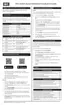
Item Number P-Kit Number Description
100 P-1000 Door panel
110 P-1010 Air filter size 25 x 16 x 1
120 P-1008 Door switch, SPST-NO. 15A 125V
120 Wiring harness
130 P-1011 Supply water temperature sensor
140 P-1012 Temperature sensor and grommet
150 P-1011 Return water temperature sensor
160 P-1003 Hot water coil 2-ton unit
170 P-1005 Transformer 40VA 120V
180 P-1001 Control board
190
P-1007
Filter bracket wing nuts x 4
200 Air filter lower bracket
210 Air filter upper bracket
220
P-1017* Coil hex bolts, hex nut, washer x 2
Fan plate hex bolts, washer x 2
230 P-1004 Fan and motor assembly
240 Fan wiring grommet
250 P-1009 Sensor wiring harness
260 P-1017* Door thumb screws x 2
 Loading...