L N
5 6
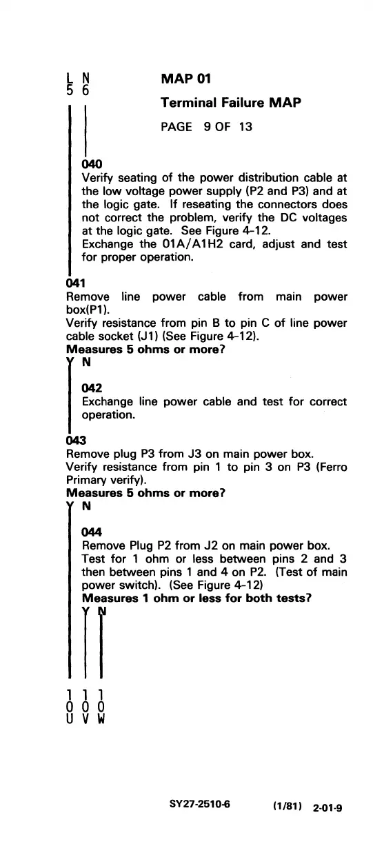
MAP
01
Terminal
Failure MAP
PAGE
9
OF
13
040
Verify seating
of
the power distribution cable at
the
low
voltage power supply (P2 and
P3)
and at
the
logic gate.
If
reseating the connectors does
not correct the
problem, verify the
DC
voltages
at the logic gate. See Figure 4-12.
Exchange the
01
AI
A 1 H2 card, adjust and test
for
proper operation.
041
Remove line power cable from main power
box(P1).
Verify resistance from pin B
to
pin C
of
line power
cable socket
(J
1)
(See
Figure 4-12).
Measures
5
ohms
or
more
1
f
:2
Exchange line power cable and
test
for
correct
operation.
043
Remove plug
P3
from
J3
on main power box.
Verify resistance from pin 1
to
pin 3 on
P3
(Ferro
Primary verify).
Measures
5
ohms
or
more
1
N
044
Remove Plug
P2
from
J2
on main power box.
Test
for
1 ohm or less between pins 2 and 3
then between pins 1 and 4 on
P2.
(Test
of
main
power switch).
(See Figure 4-12)
Measures
1
ohm
or
less
for
both
tests
1
If
1 1 1
000
U V W
SY27-2510-6
(1/81) 2-01.9
 Loading...