Do you have a question about the IBM 3278 Series and is the answer not in the manual?
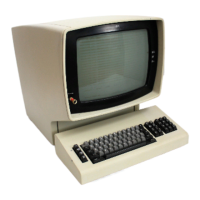
Manual covers maintenance for IBM 3278 Display Station Models 1-5.
Outlines the seven chapters and appendix of the publication.
Identifies MAP 00 as the starting point for troubleshooting.
Lists critical safety warnings related to electrical shock, high voltage, and hot components.
Provides operational cautions for handling equipment and preventing damage or intermittent failures.
Guidelines for working alone, safe power disconnection, and personal protective measures.
Specific safety instructions for handling CRTs and high voltages.
Rules for restoring safety devices, securing covers, and maintaining a clean work area.
Steps for responding to accidental electrocution and serious injuries.
Detailed instructions for performing rescue breathing on adults.
Describes station attachment, logic types (D/M), and Field Replaceable Units.
Details differences in D/M logic types and Model 5 capabilities.
Explains MSR/MHS functionality and APL/Text capabilities.
Describes selector pen function and electrical grounding requirements.
Lists static ground points to check for intermittent or erratic display operation.
Covers the unit's design for lightning protection and customer responsibility.
Outlines operation tests, FRU swapping, and MAPs as maintenance aids.
Describes operation tests and rules for using Maintenance Analysis Procedures.
Provides rules for using MAPs, including problem determination and card/connector checks.
Entry point for isolating any failure on the 3278, including logic type indicators.
Details steps for checking LEDs, FRUs, voltages, and ferrocapacitors.
Troubleshooting for blank screens, dim displays, or single lines, listing affected cards.
Steps for diagonal lines or sync problems, involving yoke and analog card adjustments.
Addresses raster problems, intensity variations, and cursor flashing.
Troubleshooting for divider lines, random data, and keyboard input problems.
Troubleshooting for incorrect characters, missing dots, and Test Mode 1 errors.
Covers keyboard failures, selector pen issues, and MSR/MHS component problems.
Guides for indicated error codes and APL/Text mode specific errors.
Lists entry/exit points and the first step for checking indicator lights.
Steps for identifying incorrect display, keyboard, subsystem, or feature failures.
Steps for checking power, fuses, and routing to other MAPs.
Procedures for exchanging fuses, the 01A/A1H2 card, and checking for shorts.
Steps for exchanging logic cards and checking low voltage and line power cables.
Procedures for verifying AC and DC voltages, including analog card adjustments.
Steps for analog card adjustments and troubleshooting voltage problems.
Troubleshooting involving power supply, logic cards, and intensity/contrast controls.
Steps for checking power distribution cables, line power cable resistance, and main power switch.
Procedures for exchanging ON/OFF switch, power assemblies, ferro transformer, and fuses.
Steps involving power supply exchange, ferro transformer, main power box, and 01A/A1H2 card exchange.
Troubleshooting for high voltage indicator, card adjustments, and low voltage power supply.
Final step involving exchanging and adjusting the 01A/A1H2 card.
Lists entry/exit points and the first step for checking indicator lights.
Steps for removing feature cards and identifying if the problem persists.
Steps for checking coax cable, cursor, divider line, and screen blanking.
Procedures for exchanging the 01A/A1H2 card, checking display normality, size, and focus.
Steps for verifying analog adjustments, exchanging cards, and checking for flashing displays.
Steps related to intensity control, blank screens, and card exchanges.
Procedures for checking fuse F1 and observing CRT filament light.
Steps for exchanging the CRT, checking for cable shorts, and verifying operation.
Procedures for checking CRT socket connections, raster appearance, and single line displays.
Steps for exchanging various cards and checking for cursor presence.
Troubleshooting for divider lines, security key position, and wiring to key switches.
Steps for checking cursor appearance, test patterns, and exchanging cards.
Procedures for test modes, correcting display patterns, and exchanging cards.
Steps for verifying controller communication and checking display alignment.
Procedures for display adjustments, intensity/contrast controls, and card exchanges.
Steps for checking the Test/Normal switch and verifying screen content.
Procedures for checking character readability, exchanging cards, and verifying case switch settings.
Steps for resistance checks, card exchanges, and verifying character display sequence.
Procedures for removing feature cards, testing keyboard exercise, and routing to MAP 03.
Steps for checking controller communication, exchanging cards, and routing to MAP 05.
Lists entry/exit points and initial steps for mechanical and key checks.
Procedures for checking keyboard cable connectors, logic card, and ID jumpers.
Steps for card exchanges, verifying operation, and identifying clicker failures.
Procedures for checking clicker sound, exchanging logic cards, and handling system-disabled clickers.
Lists entry/exit points and initial steps for identifying feature cards and isolating problems.
Steps to identify if selector pen, MSR, ECS/TEXT, PS, or security keylock caused the error.
Troubleshooting for audible alarms, intermittent issues, and routing to other MAPs.
Procedures for exchanging cards and checking for audible alarm issues.
Steps for identifying features, checking switch settings, and verifying operation.
Procedures for exchanging PS and ECS feature cards and handling font issues.
Steps for exchanging ECS cards and PS cards, and checking for corrected trouble.
Details on ECS card switch settings and checking for error codes.
Procedures for exchanging ECS cards, pluggable modules, and verifying cable connections.
Steps for reinstalling cards, checking MSR operation, and verifying fuses.
Procedures for verifying voltages related to the MSR component.
Steps for testing MSR with a test card, exchanging logic cards, and verifying test success.
Procedures for exchanging logic cards and returning the unit to the customer.
Steps for selector pen cleaning, voltage checks, and exchanging selector pen feature cards.
Procedures for exchanging the selector pen and isolating audible alarm issues.
Lists entry/exit points and initial steps for checking indicator lights and switches.
Steps for removing feature cards and identifying if the problem persists.
Procedures for checking the security key, using the error log, and exchanging the 01A/A1G2 card.
Steps for testing coax cable resistance and checking card gate connections.
Procedures for exchanging cards, checking error codes, and identifying feature-related errors.
Steps for checking coax connectors, identifying features, and exchanging cables.
Procedures for exchanging cards, routing to other MAPs, and disconnecting the keyboard.
Steps for exchanging cards, cables, and routing to other MAPs.
Overview of maintenance aids including switches, indicators, and diagnostic tests.
Explains operation tests for failure determination and verification, including offline and online tests.
Describes Test Mode 1 for checking character generator, storage, and control logic.
Explains Test Mode 2 for testing keyboard scan codes and character display replacement.
Describes Test Mode 2 for Japanese Katakana keyboards and double-character entry.
Describes Test Mode 2 for Japanese English keyboards and double-character entry.
Explains Test Mode 3 for logic area tests and data paths, with key sequences.
Details character results based on keyboard type and model for Test Mode 3.
Describes Test Mode 3 steps involving security keylock and clearing status.
Details Test Mode 3 steps for cursor behavior, test patterns, and key sequences.
Explains Test Mode 3 key operations affecting cursor movement and display changes.
Describes Test Mode 3 steps for cursor movement and pattern display verification.
Covers Test Mode 3 steps for intensity control and font verification.
Details Test Mode 3 steps for power-on reset and clearing display positions.
Explains Test Mode 3 steps for character entry and cursor movement based on key presses.
Concludes offline tests and refers to online tests for features.
Lists eight selectable online tests for the 3278 when attached to 3274 or 3276 control units.
Describes how to start tests, select test numbers, and specify port addresses.
Covers re-entering tests if X symbol appears and interpreting test result indicators.
Objective of Test 0 is to determine overall terminal functionality.
Allows operator testing of selector pen and keyboard functions, displays test pattern.
Defines test pattern lines and shows the actual test pattern display.
Steps for testing the selector pen feature using touch input.
Procedures for interactive testing of MSR, ECS, and PS features.
Shows the format of the error log for the 3274 control unit.
Lists common error codes for the 3274 and explains their meaning.
Illustrates the error log format and how it's displayed for the 3276 control unit.
Lists common error codes for the 3276 control unit and provides an example.
Describes the PS feature test pattern and notes on display variations for different models.
Lists error codes and corresponding repair actions for the 3274 control unit.
Lists error codes and corresponding repair actions for the 3276 control unit.
Illustrates and labels switches and indicators on the display station.
Shows switches and indicators, specifically for Katakana models.
Steps for disabling vertical deflection, removing cone shield, and aligning the yoke.
Details CRT components, yoke adjustments, and grounding clips.
Guides for centering, width adjustment, and analog card potentiometers.
Specific adjustments for Model 5, intensity control, and focus adjustment.
Preparation steps for adjusting the +44 V power supply, including jumper connections.
Steps for adjusting voltage when it's below the target range, identifying potential causes.
Steps for adjusting voltage when it's above the target range, identifying potential causes.
Instructions for removing front, side, and top/rear covers for access.
Steps for removing the low-voltage power supply and AC capacitor.
Steps for removing the prime power box and ferrotransformer.
Procedure for removing the high-voltage power supply, including CRT anode lead handling.
Identifies fuse locations and general procedures for card/connector removal.
Instructions for removing and exchanging internal connectors and coax cables.
Detailed steps for removing and inserting cards using extractor levers and proper seating.
Procedure for removing and reinstalling circuit board segments with alignment considerations.
Safety warnings for handling CRTs and initial steps for removal.
Detailed steps for removing the CRT, including disconnecting leads, removing shields, and handling holding nuts.
Cautions regarding CRT weight, handling, and support during removal and installation.
Steps for disconnecting yoke cable, removing CRT socket, cone shield, and yoke assembly.
Instructions for separating and reinstalling yoke and centering magnet assemblies, noting orientation.
Procedures for removing/installing grounding clips and tightening yoke clamp screws.
Notes that operator controls are mounted to the CRT mask assembly.
Steps for removing CRT frame assembly covers and mask.
Procedures for removing On/Off switch, intensity/contrast controls, and indicator cards.
Instructions for removing/reinstalling audible alarm and security keylock assemblies.
Lists required equipment and introduces procedures for keyboard unit service.
Steps for disconnecting the keyboard and removing the top cover.
Steps for disconnecting keyboard and clicker connectors and removing the assembly.
Procedures for removing clicker assembly, key buttons, and key modules.
Steps for installing a new key module, cleaning the circuit board, and aligning assemblies.
Steps for removing and reinstalling the logic card assembly from the keyboard.
Procedures for removing and reassembling the selector pen's lens assembly.
Detailed steps for unscrewing the cone-shaped tip and reassembling the lens assembly.
Describes MSR and MHS devices, their components, and customer responsibility for maintenance.
Lists defects preventing accurate reading and recommends head element cleaning.
Defines Analog card, Attribute, Bell, and Blanking terms.
Defines Coax, Cone shield, Contrast, and Cursor terms.
Defines (D) logic type and Divider scan terms.
Defines Dual intensity, Ferro, Filament, and Flyplate terms.
Defines (M) logic type, Mask, Neck, and Prime terms.
Defines Raster, Security Keylock, and Sweep terms.
| Display Type | CRT |
|---|---|
| Character Set | EBCDIC |
| Screen Size | 12 inches |
| Display Colors | Monochrome |
| Connectivity | Coaxial cable |
| Keyboard | Detachable |