© Copyright IBM Corp. 2000 3
Chapter 2. System board features
This section includes information about system board features.
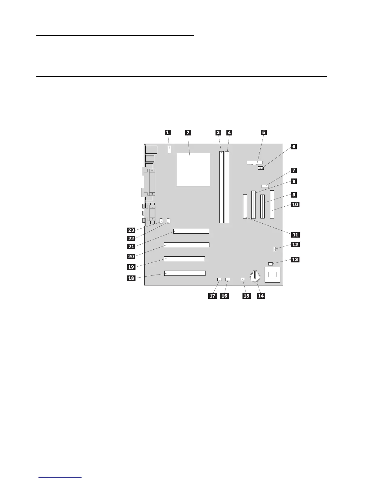
System board layout for the NetVista A40 and A40p computer
The system board might look slightly different from the one shown.
Note: A diagram of the system board, including switch and jumper settings, is
attached to the computer cover.
Þ1Ý Fan connector 2 Þ13Ý Fan connector 1
Þ2Ý Microprocessor Þ14Ý Battery
Þ3Ý DIMM 1 Þ15Ý SCSI adapter LED connector
Þ4Ý DIMM 2 Þ16Ý Alert on LAN connector
Þ5Ý Power LED connector Þ17Ý Wake on LAN connector
Þ6Ý RFID connector Þ18Ý PCI slot 3
Þ7Ý Front USB connector Þ19Ý PCI slot 2
Þ8Ý Secondary IDE connector Þ20Ý PCI slot 1
Þ9Ý Diskette drive connector Þ21Ý AGP slot
Þ10Ý Primary IDE connector Þ22Ý CD-ROM audio connector
Þ11Ý Power supply connector Þ23Ý Speaker connector
Þ12Ý Clear CMOS/recovery jumper
 Loading...


