EasyManuals Logo

IBM NetVista Technical Information Manual

IBM NetVista
72 pages
To Next Page IconTo Next Page
To Previous Page IconTo Previous Page
Page #39 background imageLoading...
Page #39 background image
© Copyright IBM Corp. 2000 29
Appendix A. Connector-pin assignments
The following figures show the pin assignments for various system board connectors.
External connectors
The following information shows the pin assignments for external connectors.
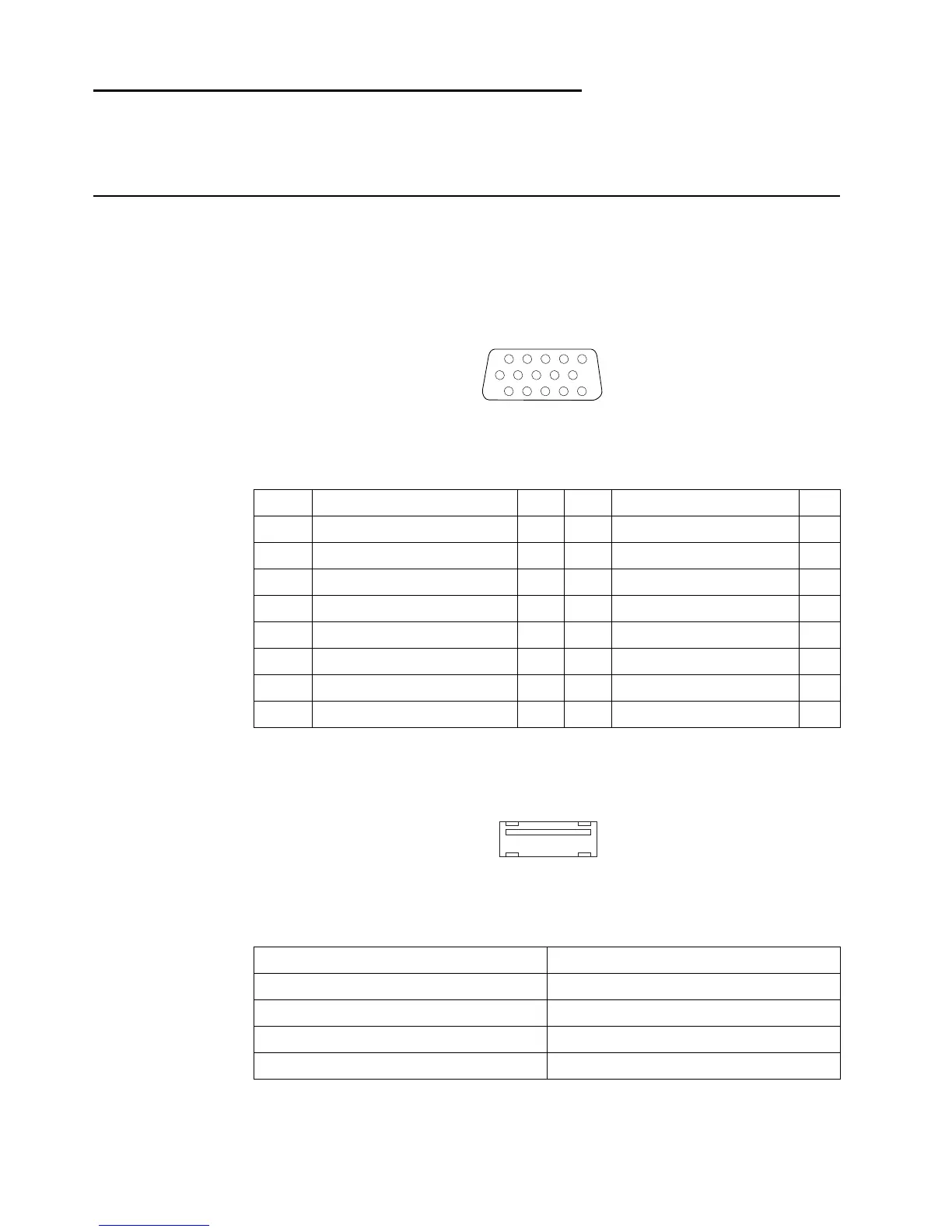
Monitor connector
USB port connectors
Table 10. Monitor connector-pin assignments
Pin Signal I/O Pin Signal I/O
1 Red O 9 +5 V dc, used by DDC2B
2 Green I 10 Ground
3 Blue O 11 Monitor ID 0 - not used
4 Monitor ID 2 - not used I 12 DDC2B data I/O
5 Ground 13 Horizontal sync O
6 Red ground 14 Vertical sync O
7 Green ground 15 DDC2B clock I/O
8 Blue ground
1
6
11
15
Table 11. USB port connector-pin assignments
Pin Connector
1VCC
2 Data
3+Data
4 Ground
4
3
2
1

Table of Contents

Other manuals for IBM NetVista

Questions and Answers:

Question and Answer IconNeed help?

Do you have a question about the IBM NetVista and is the answer not in the manual?

IBM NetVista Specifications

General IconGeneral
CategoryDesktop
ModelNetVista
Processor TypeIntel Celeron
Memory TypeSDRAM
Optical DriveCD-ROM, DVD-ROM, or CD-RW
GraphicsIntegrated Intel graphics
AudioIntegrated audio
Network10/100 Ethernet
Operating SystemWindows 2000, Windows XP (Varies by model)
Expansion SlotsPCI
PortsUSB, serial, parallel, VGA, audio in/out

Related product manuals