32 NetVista™ Technical Information Manual
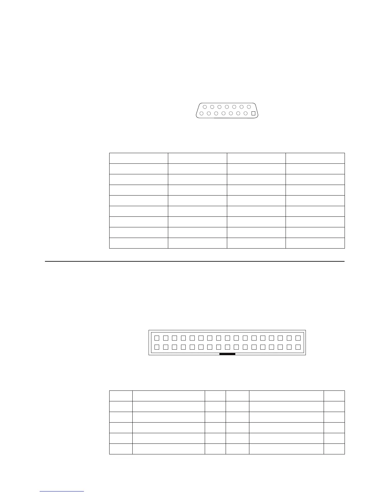
MIDI/joystick connector
The external MIDI/joystick connector attaches to the system board through a signal
cable that connects to an internal connector on the system board. The following
illustration shows the external connector.
Internal connectors
The following figures show the connector-pin assignments for various internal
connectors on the system board and memory card.
Diskette drive connector
Table 17. MIDI/Joystick external connector-pin assignments
Pin Signal Pin Signal
1+5 v dc9+5 v dc
2 JAB1 10 JBB1
3 JACX 11 JBCX
4 Ground 12 MIDI out
5 Ground 13 JBCY
6 JACY 14 JBB2
7 JAB2 15 MIDI in
8+5
1
915
8
Table 18. Diskette drive connector-pin assignments
Pin Signal I/O Pin Signal I/O
1 Ground I 18 Direction in#
2 High density select O 19 Ground
3 Ground 20 Step# O
4 Not connected 21 Ground
5 Ground 22 Write data# O
1
2
34
33
 Loading...


