Chapter 2. Architecture and technical overview 109
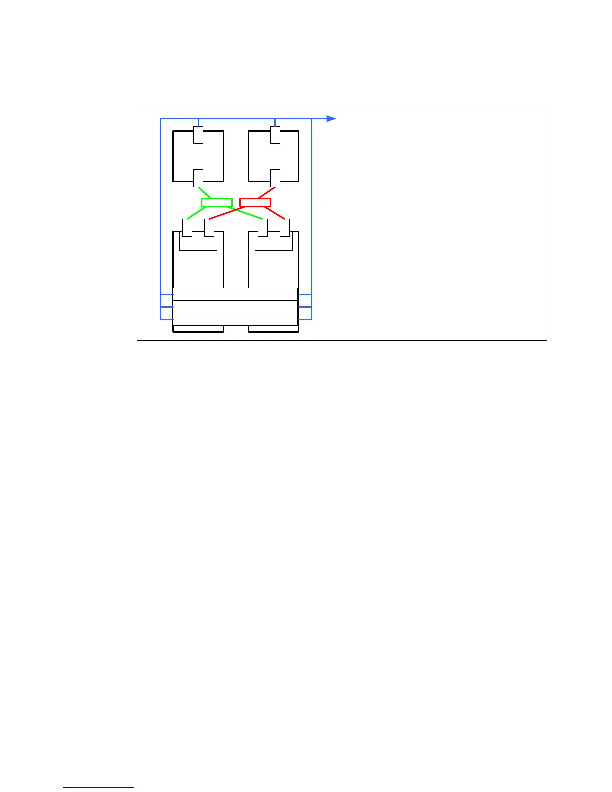
Figure 2-39 shows a redundant HMC and redundant service processor connectivity
configuration.
Figure 2-39 Redundant HMC connection and redundant service processor configuration
In a configuration with multiple systems or HMC, the customer is required to provide switches
or hubs to connect each HMC to the server FSP Ethernet ports in each system:
One HMC should connect to the port labeled HMC Port 1 on the first two CEC drawers
of each system.
A second HMC must be attached to HMC Port 2 on the first two CEC drawers of
each system.
This solution provides redundancy for both the HMC and the service processors.
HMC1 HMC2
CEC 1 CEC 2
1 2
FSP
1 2
FSP
LAN 1 LAN 2
LPAR 1
LPAR 2
LPAR 3
eth0 eth1
eth0 eth1
LAN1 – Hardware management network for
first FSP ports (private)
LAN2 – Hardware management network for
second FSP ports (private), separate
network hardware from LAN1
LAN3 - Open network for HMC access and
dLPAR operations
LAN3 – Open network
 Loading...

