110 IBM Power 770 and 780 (9117-MMD, 9179-MHD) Technical Overview and Introduction
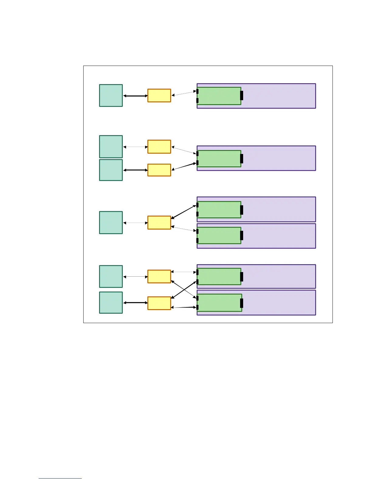
Figure 2-40 describes the four possible Ethernet connectivity options between HMC and
FSPs.
Figure 2-40 Summary of HMC to FSP configuration option depending on number of CEC
For details about redundant HMC, see Hardware Management Console V7 Handbook,
SG24-7491.
Drawer 1
FSP Car d
Enet 1
Enet 2
HU B 0
Configur ation #1 – Single drawer a nd one HMC
No te : HUB is o ptio na l.
Customer can have a direct connection to the FSP card.
HMC #1
Enet
Drawer 1
FSP Car d
Enet 1
Enet 2
HU B 0
Configur ation #2 – Single drawer a nd two HMCs
No te : HUB is o ptio na l.
HMC #1
Enet
HU B 1HMC #2
Enet
Drawer 1
FSP Car d
Enet 1
Enet 2
Configur ation #3 – Multi-drawe r with one HMC
HU B 0HMC #1
Enet
Drawer 2
FSP Car d
Enet 1
Enet 2
Drawer 1
FSP Car d
Enet 1
Enet 2
Configur ation #4 – Multi-drawe r with two H MCs
Drawer 2
FSP Car d
Enet 1
Enet 2
HU B 1
HMC #2
Enet
HU B 0HMC #1
Enet
 Loading...

