Procedure
1. Ensure that the system has completed booting and the system image is running.
2. Connect the supplied console cable (a rollover RJ-45-to-RJ-45 cable) to the console port.
3. Connect the other end of the console cable to the supplied RJ-45-to-DB-25 adapter.
4. Connect the RJ-45-to-DB-25 adapter to the DB-25 port on the modem.
5. Initialize and congure the modem as specied in the Fabric Manager Fundamentals Conguration
Guide and the NX-OS Fundamentals Conguration Guide.
Connecting the Management Ports
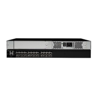
The auto-sensing 10/100/1000 Mbps Ethernet management ports are located on the left side of the front
panel (labeled MGMT ETH0 and MGMT ETH1), below the console port. MGMT ETH0 is the default Ethernet
management port (interface mgmt0). This port is used for out-of-band management and data streaming
to remote receivers.
Note: The MGMT ETH1 port is disabled in Cisco MDS NX-OS Release 8.3(1).
Use a modular, RJ-45, straight-through UTP cable to connect the management ports to an external hub or
switch. To connect to a router, use a crossover cable.
Connecting to a Fibre Channel Port
The Fibre Channel ports in the IBM SAN48C-6 switch are compatible with FC LC-type ber-optic SFP+
transceivers and cables (see the Removing and Installing Cables into SFP Transceivers section). You can
use these ports to connect to the SAN or for in-band management. For information about conguring the
switch for in-band management, see the Fabric Manager Fundamentals Conguration Guide or the NX-OS
Fundamentals Conguration Guide.
Each transceiver must match the transceiver at the other end of the cable, and the cable must not exceed
the stipulated cable length for reliable communications. SFP+ transceivers can be ordered either
separately or with the IBM SAN48C-6 switch.
Warning: Class 1 laser product
. Statement 1008
Warning: Invisible laser radiation may be emitted from disconnected bers or connectors. Do
not stare into beams or view directly with optical instruments. Statement 1051
Note: Wear an ESD wrist strap connected to the chassis when handling transceivers. Keep optical
connectors covered when not in use, and do not touch connector ends. The ber-optic connectors must
be free of dust, oil, and other contaminants.
Removing and Installing Cables into SFP Transceivers
CAUTION:
To prevent damage to the ber-optic cables, do not place more tension on them than
the rated limit and do not bend to a radius of less than one inch (2.5 cm) if there is no tension in
the cable, or two inches (5 cm) if there is tension in the cable.
Installing a Cable into an SFP Transceiver
About this task
CAUTION:
To prevent possible damage to the cable or transceiver, install the transceiver in the
port before installing the cable in the transceiver.
To install a cable into a transceiver, follow these steps:
32
IBM Storage Networking: IBM Storage Networking SAN48C-6 32 Gbps 48-Port Fibre Channel Switch
Installation, Service, and User Guide

 Loading...