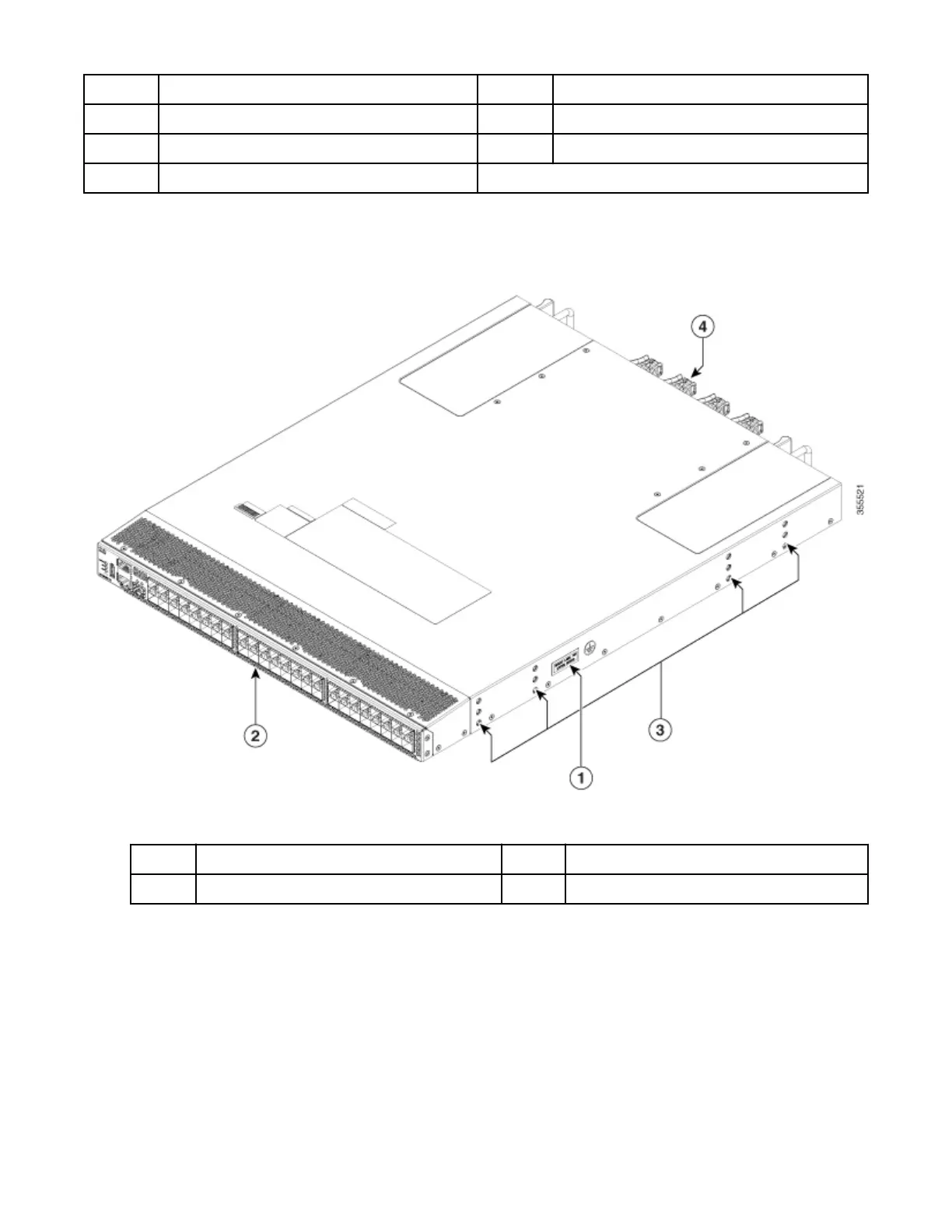
2 Power supply unit fan 7 Power supply units (2 units)
3 Power supply unit handle 8 Chassis fan modules (4 units)
4 Unswitched power receptacle 9 Chassis fan module release latches (8)
5 Power supply unit latch release
Side View
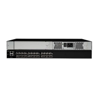
The following gure shows the side view of a IBM SAN48C-6 Switch:
Figure 3. Side View of the IBM SAN48C-6 Switch
1
Grounding point 3 Rack mounting holes
2 Port side of the switch 4 Rear side of the switch
Fan Modules
The IBM SAN48C-6 Switch fan modules have a xed handle for insertion and removal from the chassis.
The IBM SAN48C-6 Switch requires a minimum of two operating fan modules to prevent automatic
shutdown. It supports up to four fan modules. This provides redundancy for uninterrupted operation in
the event of fan module failure. The IBM SAN48C-6 Switch fan modules are hot-swappable to also allow
swapping out of a fan module during operation for uninterrupted operation. During a fan module
replacement, the internal airflow through the chassis is changed. If the internal airflow is disrupted for too
long, the preset temperature thresholds will be exceeded and the system will automatically shut down to
prevent permanent damage.
Chapter 1. Overview of the IBM SAN48C-6 Fibre Channel Switch
3

 Loading...