+5
+4
+3
+2
+1
0
,'>-
I).
//-
')0.
IA
I).
I'-~
/L~
~~
ILl
/1
\
/L_\
/
/'L
_\
/ \
/ \
/
\
/ \ /
\
/
/
\
\ /
\
/ \ / \ /
\
\ /
/
1/
V
V v
.;
. ' ,
A.
Too
much
ratio
change
---------
..
~~.;::.
<
....
/:;.,
..
~.,
.....
:.:. ',-"
.:
~
-
..
>~
~
.
.
......
,<.-."
B. Insufficient
ratio
change
--------------i~~
..
'::.,'~
+5 +4 +3 +2
+ 1 0 -1
-2
-3
-4
-5
I)
A
I>
/\
'>
'>
I)
1\
A
I\:·.,:<~::.·i.::'.:·:·
/ L \ /
l~
I L \ I ,!.\ / L
~
/
L~
/ L
~
/
("
l
...
:
..
:.-::A.·
..
<>
..
'.'.';;
..
·.·
..
:::·.'
...
::::'.·;
..
:
.;:.'
/ \ / \ I
"\
/ \ I \ I \ I \ I ' / ::i!f?}'':;:::' .:'.
/ \ / \ I
,/
\ I \ I
,I
\
I'
/
>:::'.:'
:\'
.....
:.:
I
\!
V V V V V V
;.:'.';,,':-';;>'.,::-',(':',.
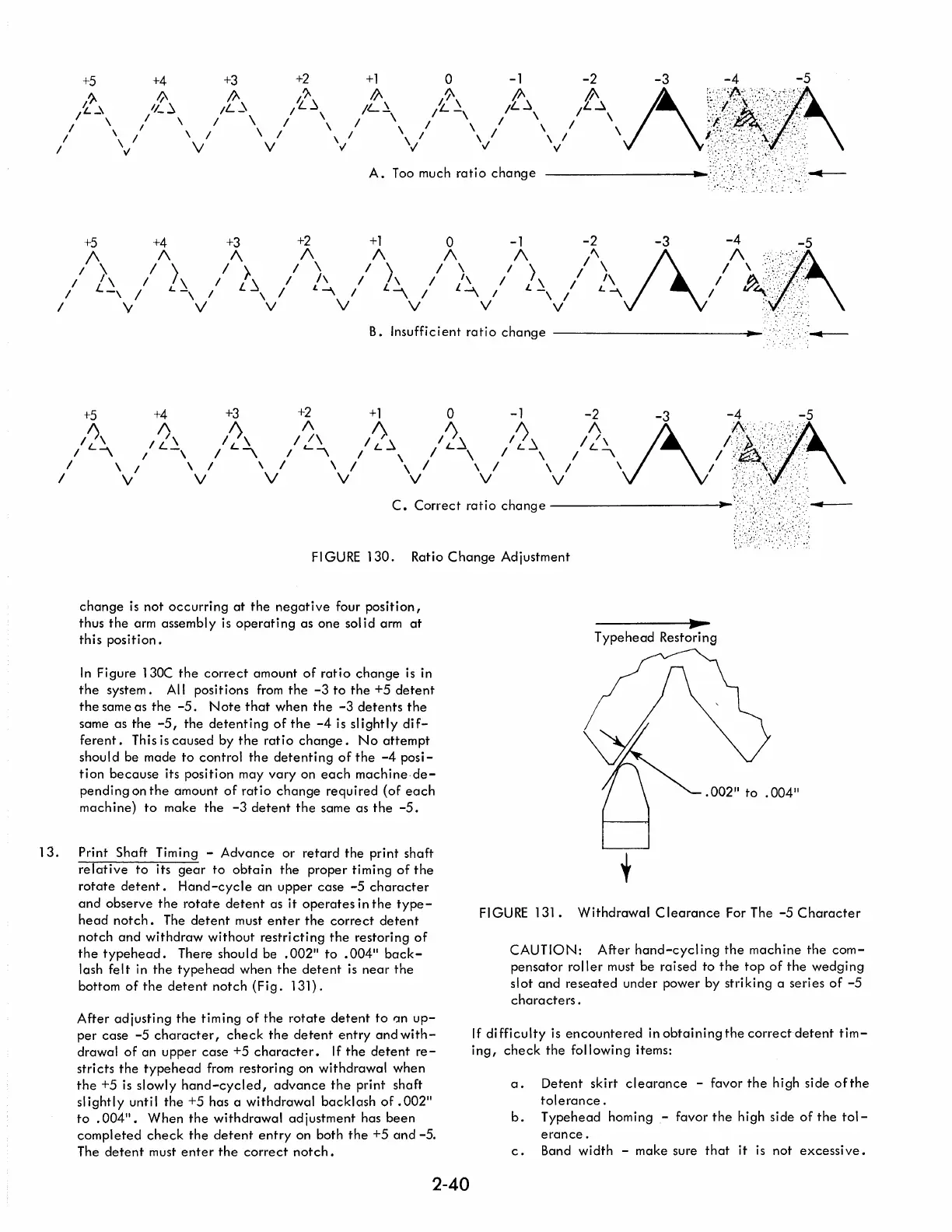
FI
GURE
130.
Ratio
Change
Adjustment
change
is
not
occurring
at
the
negative
four
position,
thus
the
arm assembly
is
operating
as one sol id arm
at
this
position.
In
Figure 130C
the
correct
amount
of
ratio
change
is
in
the
system. All positions
from
the
-3
to
the
+5
detent
the
same as
the
-5.
Note
that
when
the
-3
de
tents
the
same as
the
-5,
the
detenting
of
the
-4
is
slightly
dif-
ferent.
This
is
caused
by
the
ratio
change.
No
attempt
should be made
to
control
the
detenting
of
the
-4
posi-
tion
because
its position may
vary
on
each
machine·de-
pending
on
the
amount
of
ratio
change
required
(of
each
machine)
to
make
the
-3
detent
the
same as
the
-5.
13.
Print Shaft Timing -
Advance
or
retard
the
print shaft
relative
to
its
gear
to
obtain
the
proper timing
of
the
rotate
detent.
Hand-cycle
an
upper case
-5
character
and
observe
the
rotate
detent
as
it
operates
in
the
type-
head
notch.
The
detent
must
enter
the
correct
detent
notch
and
withdraw
without
restricting
the
restoring
of
the
typehead.
There should be
.002"
to
.004"
back-
lash
felt
in
the
typehead
when
the
detent
is
near
the
bottom
of
the
detent
notch
(Fig.
131).
After
adjusting
the
timing
of
the
rotate
detent
to
IJn
up-
per
case
-5
character,
check
the
detent
entry
and
with-
drawal
of
an upper
case
+5
character.
If
the
detent
re-
stricts
the
typehead
from restoring on withdrawal when
the
+5
is
slowly
hand-cycled,
advance
the
print shaft
slightly
until
the
+5 has a
withdrawal
backlash
of
.002"
to
.004".
When
the
withdrawal
adjustment
has
been
completed
check
the
detent
entry
on both
the
+5
and
-5.
The
detent
must
enter
the
correct
notch.
2-40
Typehead
Restoring
FI
GURE
131.
Withdrawal
Clearance
For The
-5
Character
CAUTION:
After
hand-cycl
ing
the
machine
the
com-
pensator
roller
must be raised to
the
top
of
the
wedging
slot
and
reseated
under power by striking a series
of
-5
characters.
If
di
fficulty
is
encountered
in
obtaining
the
correct
detent
tim-
ing,
check
the
following items:
a.
Detent
skirt
clearance
- favor
the
high side
ofthe
tolerance.
b.
Typehead homing - favor
the
high side
of
the
tol-
erance.
c.
Band width - make sure
that
it
is
not
excessive.

 Loading...


