Be careful when you are replacing the hardware components that are located in the
back of the system that you do not inadvertently disturb or remove any cables that
you are not instructed to remove.
CAUTION:
Some laser products contain an embedded Class 3A or Class 3B laser diode.
Note the following information: laser radiation when open. Do not stare into the
beam, do not view directly with optical instruments, and avoid direct exposure
to the beam. (C030)
Perform the following steps to remove and then replace an SFP transceiver:
1. Carefully determine the failing physical port connection.
Important: The Fibre Channel links in the enclosures are supported with both
longwave SFP transceivers and shortwave SFP transceivers. A longwave SFP
transceiver has some blue components that are visible even when the SFP
transceiver is plugged in. You must replace an SFP transceiver with the same
type of SFP transceiver that you are replacing. If the SFP transceiver to replace
is a longwave SFP transceiver, for example, you must replace with another
longwave SFP transceiver. Removing the wrong SFP transceiver might result in
loss of data access.
2. Remove the optical cable by pressing the release tab and pulling the cable out.
Be careful to exert pressure only on the connector and do not pull on the
optical cables.
3. Remove the SFP transceiver. There are a number of different handling or
locking mechanisms that are used on the SFP transceivers. Some SFP
transceivers might have a plastic tag. If so, pull the tag to remove the SFP
transceiver.
Important: Always check that the SFP transceiver that you replace matches the
SFP transceiver that you remove.
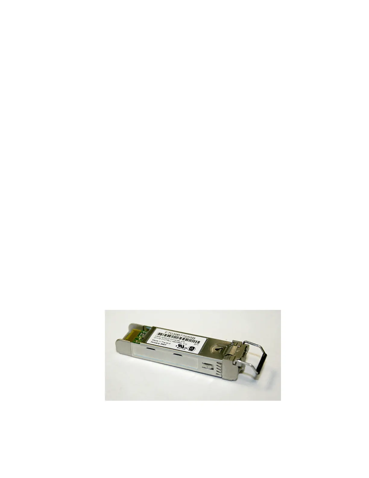
4. Push the new SFP transceiver into the aperture and ensure that it is securely
pushed home. The SFP transceiver usually locks into place without having to
swing the release handle until it locks flush with the SFP transceiver. Figure 54
illustrates an SFP transceiver and its release handle.
5. Reconnect the optical cable.
6. Confirm that the error is now fixed. Either mark the error as fixed or restart the
node depending on the failure indication that you originally noted.
svc00418
Figure 54. SFP transceiver
Chapter 5. Control enclosure 213
 Loading...


