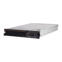
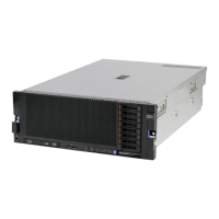
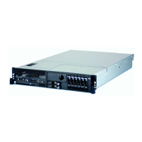
Connecting the cables
The following illustration shows the locations of the input and output connectors
on the front of the server.
Rack
release
latch
0 1 2 3 4 5 6 7 8 9 10 11 12 13 14 15
Drive bays
Video
connector
USB 1
connector
USB 2
connector
Operator information
panel release latch
Rack
release
latch
Operator
information
panel
Power-on
button
and LED
Optical drive
activity LED
Optical drive
eject button
Drive activity
LED (green)
Drive status
LED (amber)
Scalability
LED
The following illustration shows the locations of the input and output connectors
on the rear of the server.
PCI
slot 1
PCI
slot 2
PCI
slot 3
PCI
slot 4
PCI
slot 5
Power
supply 3
Power
connectors
System
management
Ethernet
connector
Video Serial
connector
USBs
3 - 4
USBs
5 - 6
Ethernet 1 Ethernet 2
Power
supply 1
Power
supply 2
Power
supply 4
QPI
port 1
QPI
port 2
You must turn off the server before you connect or disconnect cables.
See the documentation that comes with any external devices for additional cabling
instructions. It might be easier for you to route cables before you connect the
devices to the server.
For information about cabling the server and MAX5 in a rack cabinet, see the
documentation that comes with the QPI cabling option and the EXA cabling
option.
116 System x3690 X5 Types 7147, 7148, 7149, and 7192: Installation and User's Guide

 Loading...


