Installing the front adapter-retention bracket
To install the front adapter-retention bracket, complete the following steps:
1. Insert one of the hinge pins on the front adapter-retention bracket into the metal
hinge point on the fan cage assembly.
2. Rotate the other hinge pin on the front adapter-retention bracket into position
and push the hinge pin into the other metal hinge point. The hinge pin will
protrude through the hole in the metal hinge point when the adapter-retention
bracket is seated correctly.
3. Reinstall any adapters that you removed earlier.
4. Close the front and rear adapter retention brackets.
5. Install the side cover (see “Installing the side cover” on page 53).
6. Lock the side cover.
7. Reconnect the external cables and power cords; then, turn on the attached
devices and turn on the server.
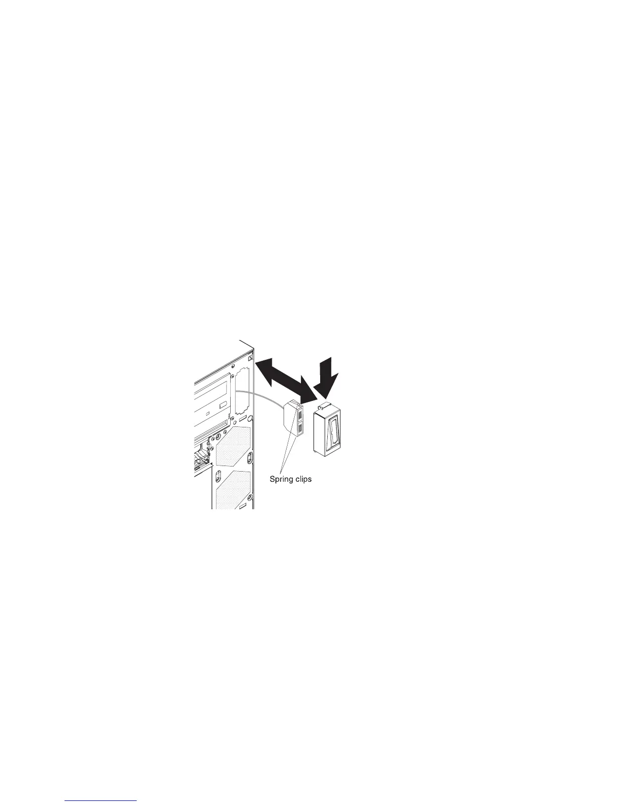
Installing the front USB connector assembly
To install the front USB connector assembly, complete the following steps:
1. Carefully insert the front USB cable through the opening in the front of the
chassis.
2. Squeeze the spring clips on the sides of the front USB connector assembly and
insert the assembly into the housing through the back of the housing.
3. Place the bottom edge of the housing into the bottom of the opening in the
chassis; then, tilt the top of the housing into position until it clicks into place.
4. Reroute and connect the front USB cable to the system board (see
“System-board internal connectors” on page 9 for the location of the front USB
connector).
5. Install the upper bezel (see “Installing the upper bezel” on page 57).
6. Install the lower bezel (see “Installing the lower bezel” on page 55).
7. Install the side cover (see “Installing the side cover” on page 53).
8. Lock the side cover if you unlocked it during removal.
9. Reconnect the external cables and power cords; then, turn on the attached
devices and turn on the server.
Chapter 4. Removing and replacing server components 93
 Loading...


