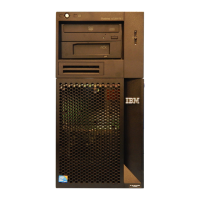
Do you have a question about the IBM x3200 M2 Type 4367 and is the answer not in the manual?
Lists related documents provided with the server, including Installation Guide, User Guide, Rack Installation Instructions, Safety Information, and Warranty and Support Information.
Provides a summary of the server's features and specifications, including microprocessor, memory, drives, power, environment, and electrical input.
Describes server controls, light-emitting diodes (LEDs), and how to turn the server on and off, covering front and rear views.
Illustrates and describes system-board internal and external connectors, optional device connectors, LEDs, and jumpers.
Provides instructions for updating server firmware, including BIOS code, VPD code, and device drivers from the IBM Web site.
Details configuration programs like Configuration/Setup Utility, ServerGuide Setup and Installation CD, and mini-BMC utility programs.
Categorizes replaceable components into Tier 1 CRU, Tier 2 CRU, and FRU, with a detailed parts listing table.
Lists product recovery CDs and their corresponding CRU part numbers for various Microsoft Windows Server editions.
Provides safety information and lists IBM power cord part numbers used in specific countries and regions.
Provides essential information before removing or replacing components, including safety and firmware updates.
Explains precautions to prevent damage to sensitive devices from electrostatic discharge during handling.
Details the procedures for removing and replacing Tier 1 Customer Replaceable Units (CRUs), starting with the side cover.
Provides step-by-step instructions for safely removing an adapter from the server's expansion slot.
Illustrates drive bay locations and provides procedures for removing and installing internal drives like CD/DVD and tape drives.
Describes the procedure for removing hot-swap hard disk drives, emphasizing system cooling precautions.
Details the steps for removing a dual inline memory module (DIMM) from the server's memory slot.
Provides instructions on how to remove the rear system fan, including disconnecting cables and handling rubber grommets.
Explains how to remove the hard disk drive fan assembly, including disconnecting the cable and removing drives.
Details the procedure for removing the simple-swap SATA backplate from the hard disk drive cage.
Provides instructions for removing the SAS/SATA hard disk drive backplane from the hard disk drive cage.
Describes how to remove the front-panel assembly, including bezel removal and cable disconnection.
Outlines the steps to remove the optional mini-PCI-X enablement card from the system board.
Details the procedure for removing the IBM ServeRAID-MR10i SAS/SATA controller from the server.
Provides instructions for removing the Remote Supervisor Adapter II SlimLine from its dedicated connector.
Covers the removal and replacement of Field Replaceable Units (FRUs), specifically detailing non-hot-swap power supply removal.
Explains how to remove the microprocessor and its associated fan sink, including safety precautions.
Details the steps for removing the system board, including disconnecting cables and other components.
Lists diagnostic tools available to help diagnose hardware-related problems, including POST, troubleshooting tables, LEDs, and diagnostic programs.
Explains the Power-On Self-Test (POST) process, including beep codes and error messages indicating problems.
Describes POST beep codes, their meanings, and suggested actions to correct detected problems.
Details the three types of server error logs (POST, System-event/error, BMC system event) and how to view them.
Lists POST error codes, their descriptions, and suggested actions for troubleshooting.
Provides tables that list problem symptoms and suggested actions to correct them for various components.
Illustrates system-board LEDs and explains how they help locate the source of errors.
Shows illustrations of power supply connectors and LEDs, indicating server status.
Introduces IBM Dynamic System Analysis (DSA) diagnostic programs and their capabilities.
Provides step-by-step instructions for running the DSA Preboot diagnostic programs.
Provides steps to take before contacting IBM for help, including checking cables and power.
Explains where to find information about IBM systems, optional devices, and troubleshooting, including Web sites.
Lists IBM Web site addresses for System x, BladeCenter, and IntelliStation information.
Details how to get telephone assistance for software issues with IBM products.
Explains how to receive hardware service through IBM resellers or IBM Services.
Lists trademarks of International Business Machines Corporation and other companies.
Provides attention notices and limits for particulates and gases to avoid server damage.
Describes the documentation format and how to request alternative formats or provide feedback.
Includes FCC, Industry Canada, Australia/New Zealand, UK, EU, Germany, and Japan emission statements.
| Processor | Intel Xeon 3000 Sequence, Intel Core 2 Duo, Intel Pentium Dual-Core |
|---|---|
| Memory Slots | 4 DIMM slots |
| Chipset | Intel 3200 |
| Storage Controller | Integrated SATA controller |
| Form Factor | Tower |
| Memory | Up to 8GB DDR2 |
| Storage | SATA |
| Hard Drive Bays | 4 |
| RAID Support | RAID 0, 1 |
| Network Controller | Integrated Broadcom Gigabit Ethernet |
| Expansion Slots | 1 PCI-Express x8, 1 PCI-Express x1, 2 PCI |
| Power Supply | 400W fixed |
| Operating System Support | Microsoft Windows Server, Red Hat Enterprise Linux, SUSE Linux Enterprise Server |
| Processor Cores | Dual-core, Quad-core (Xeon 3200 series) |


