EasyManuals Logo

IBM x3200 M2 Type 4367 User Manual

IBM x3200 M2 Type 4367
266 pages
To Next Page IconTo Next Page
To Previous Page IconTo Previous Page
Page #27 background imageLoading...
Page #27 background image
Connectors, LEDs, and jumpers
The illustrations in this section show the connectors, light-emitting diodes (LEDs),
and jumpers on the system board. The illustrations might differ slightly from your
hardware.
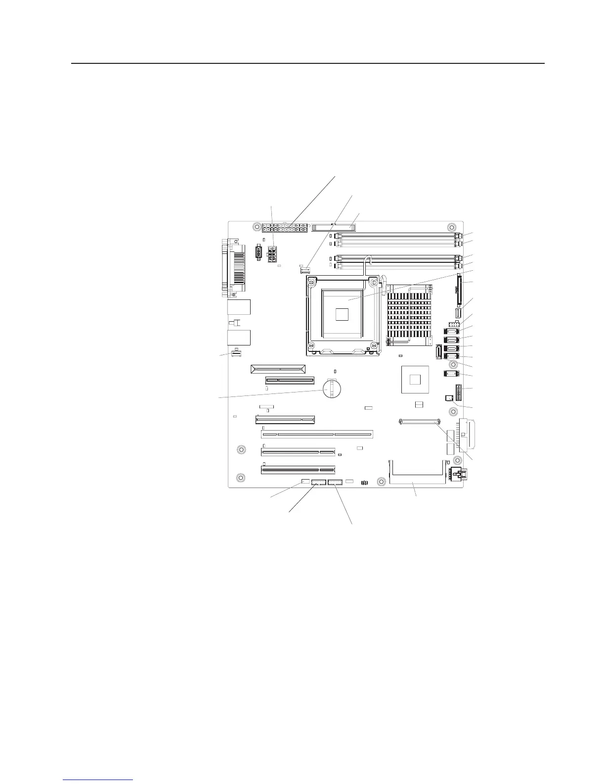
System-board internal connectors
The following illustration shows the internal connectors on the system board.
Microprocessor
power
DIMM 1
DIMM 2
DIMM 3
DIMM 4
Microprocessor
Hard disk drive fan
USB tape drive
Mini-PCI slot
Battery
System
fan connector
Main power
Microprocessor fan
(optional) External USB diskette drive
Front panel
Front USBs
SATA 0
SATA 1
SATA 2
SATA 3
SATA 4
SATA 5
Hot-swap hard
disk drive backplane
PCI-X enablement
card connector
Mini-BMC JTAG connector
Wake on LAN
Mini-BMC boot loader
Chapter 1. Introduction 9

Table of Contents

Questions and Answers:

Question and Answer IconNeed help?

Do you have a question about the IBM x3200 M2 Type 4367 and is the answer not in the manual?

IBM x3200 M2 Type 4367 Specifications

General IconGeneral
ProcessorIntel Xeon 3000 Sequence, Intel Core 2 Duo, Intel Pentium Dual-Core
Memory Slots4 DIMM slots
ChipsetIntel 3200
Storage ControllerIntegrated SATA controller
Form FactorTower
MemoryUp to 8GB DDR2
StorageSATA
Hard Drive Bays4
RAID SupportRAID 0, 1
Network ControllerIntegrated Broadcom Gigabit Ethernet
Expansion Slots1 PCI-Express x8, 1 PCI-Express x1, 2 PCI
Power Supply400W fixed
Operating System SupportMicrosoft Windows Server, Red Hat Enterprise Linux, SUSE Linux Enterprise Server
Processor CoresDual-core, Quad-core (Xeon 3200 series)

Related product manuals