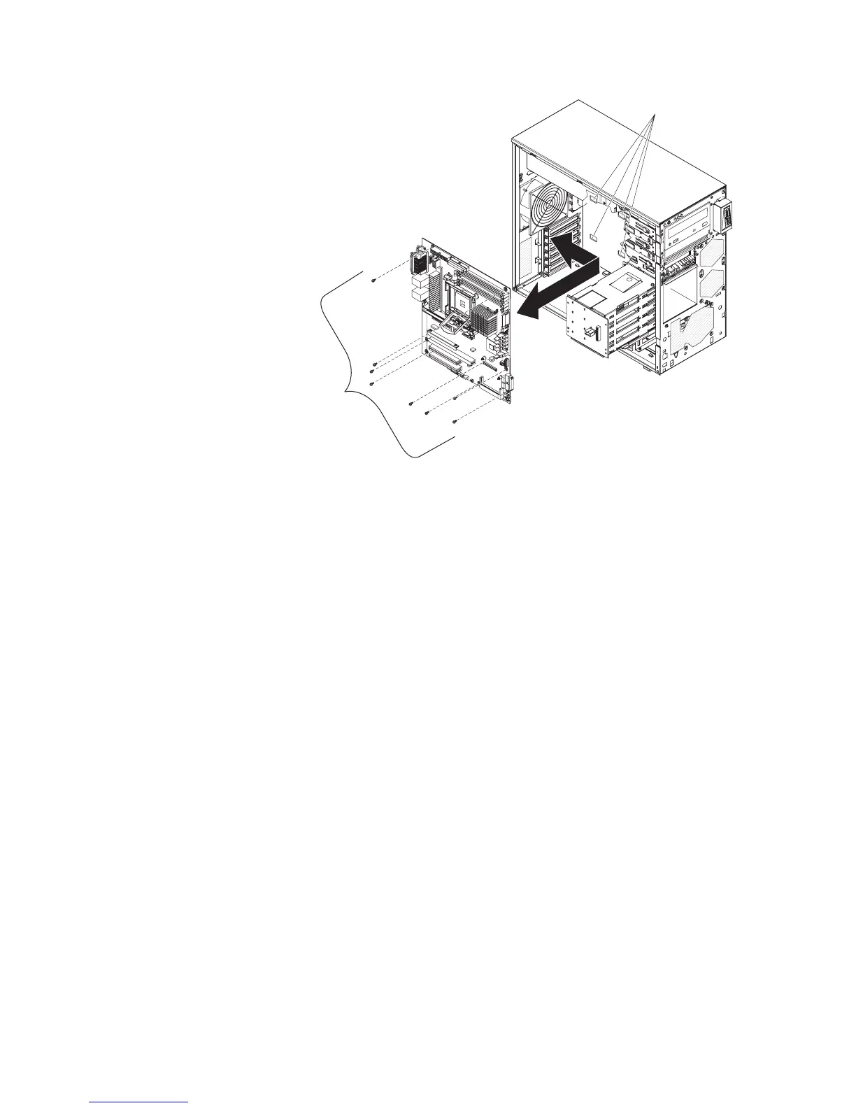
EasyManuals Logo

IBM x3200 M2 Type 4367 User Manual

IBM x3200 M2 Type 4367
266 pages
To Next Page IconTo Next Page
To Previous Page IconTo Previous Page
Page #133 background imageLoading...
Page #133 background image
System board
mounting screws
(8 places)
Fan-sink mounting
bracket slots
10. Slide the system board toward the front of the server to disengage the tabs on
the fan sink mounting bracket from the slots on the bottom of the chassis;
then, carefully lift the system board out of the server.
11. Remove the four screws that secure the fan sink retention module and fan sink
mounting bracket to the system board; then, set the fan sink retention module,
fan sink mounting bracket, and screws aside for use later.
Note: Make sure that you observe the orientation of the fan sink retention
module before you move it so that when you reinstall it, you install it in the
same orientation.
Chapter 4. Removing and replacing server components 115

Table of Contents

Questions and Answers:

Question and Answer IconNeed help?

Do you have a question about the IBM x3200 M2 Type 4367 and is the answer not in the manual?

IBM x3200 M2 Type 4367 Specifications

General IconGeneral
ProcessorIntel Xeon 3000 Sequence, Intel Core 2 Duo, Intel Pentium Dual-Core
Memory Slots4 DIMM slots
ChipsetIntel 3200
Storage ControllerIntegrated SATA controller
Form FactorTower
MemoryUp to 8GB DDR2
StorageSATA
Hard Drive Bays4
RAID SupportRAID 0, 1
Network ControllerIntegrated Broadcom Gigabit Ethernet
Expansion Slots1 PCI-Express x8, 1 PCI-Express x1, 2 PCI
Power Supply400W fixed
Operating System SupportMicrosoft Windows Server, Red Hat Enterprise Linux, SUSE Linux Enterprise Server
Processor CoresDual-core, Quad-core (Xeon 3200 series)

Related product manuals