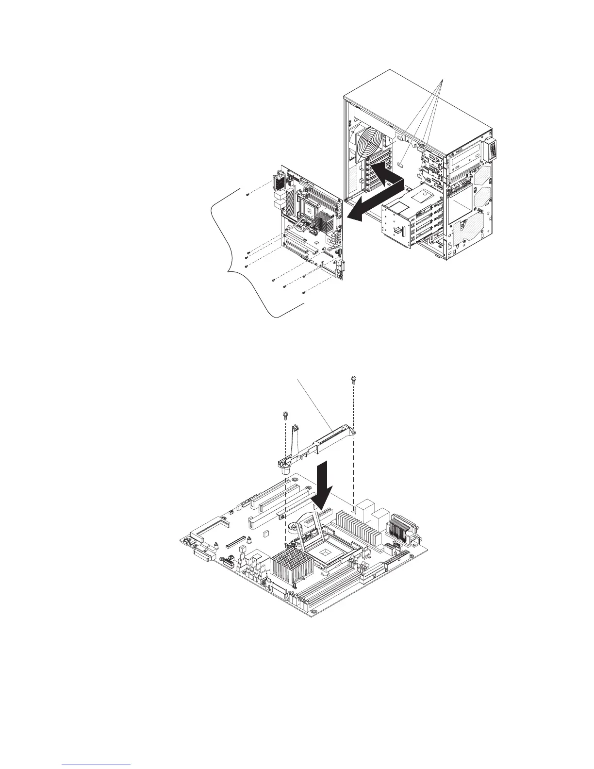
EasyManuals Logo

IBM x3200 M2 Type 4367 User Manual

IBM x3200 M2 Type 4367
266 pages
To Next Page IconTo Next Page
To Previous Page IconTo Previous Page
Page #136 background imageLoading...
Page #136 background image
System board
mounting screws
(8 places)
Fan-sink mounting
bracket slots
4. Install the eight screws that secure the system board to the chassis.
5. Reinstall the Remote Supervisor Adapter II SlimLine support bracket with the
two screws that you removed earlier.
Remote Supervisor Adapter II
SlimLine support bracket
6. Install any of the following components that you removed from the system
board:
v SAS/SATA controller (see “Installing the SAS/SATA controller” on page 97).
v Battery (see “Installing the battery” on page 77).
v DIMMs (see “Installing a memory module” on page 76).
118 System x3200 M2 Types 4367 and 4368: Problem Determination and Service Guide

Table of Contents

Questions and Answers:

Question and Answer IconNeed help?

Do you have a question about the IBM x3200 M2 Type 4367 and is the answer not in the manual?

IBM x3200 M2 Type 4367 Specifications

General IconGeneral
ProcessorIntel Xeon 3000 Sequence, Intel Core 2 Duo, Intel Pentium Dual-Core
Memory Slots4 DIMM slots
ChipsetIntel 3200
Storage ControllerIntegrated SATA controller
Form FactorTower
MemoryUp to 8GB DDR2
StorageSATA
Hard Drive Bays4
RAID SupportRAID 0, 1
Network ControllerIntegrated Broadcom Gigabit Ethernet
Expansion Slots1 PCI-Express x8, 1 PCI-Express x1, 2 PCI
Power Supply400W fixed
Operating System SupportMicrosoft Windows Server, Red Hat Enterprise Linux, SUSE Linux Enterprise Server
Processor CoresDual-core, Quad-core (Xeon 3200 series)

Related product manuals