Figures
1. Compression savings in the Volumes by Pools view .................... 9
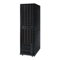
2. Example of a fully-populated XIV system model 281x-114, model 281x-214, or model 281x-314...... 13
3. Example of a minimally populated XIV system ..................... 14
4. Example of a minimally populated XIV system for model 281x-314 ............... 15
5. Rear-door heat exchanger option kit ......................... 23
6. Maximum tilt for a packaged rack is 12.5 degrees ..................... 26
7. Clearance requirements for servicing the XIV system rack .................. 32
8. Raised floor requirements ............................. 33
9. Layout and dimensions for circular cutouts ....................... 35
10. Eyebolts installed in the subfloor .......................... 35
11. Host-connections patch panel with Fibre Channel and 10 Gb Ethernet iSCSI ports .......... 49
12. Host-connections patch panel with Fibre Channel and 1 Gb Ethernet iSCSI ports .......... 50
13. Fully redundant Fibre Channel configuration with six paths to each volume ............ 56
14. Fully redundant Fibre Channel configuration with 12 paths to each volume ............ 57
15. Fully redundant Fibre Channel configuration with minimum cabling and paths to six interface modules 58
16. Remote support components ............................ 66
17. Remote support connectivity by modem ........................ 67
18. Call home routing ............................... 69
19. Typical performance of a rear-door heat exchanger, 32 kW heat load .............. 73
20. Typical performance of a rear-door heat exchanger, 20 kW heat load .............. 73
21. Cooling distribution unit that uses off-the-shelf supplier solutions ............... 78
22. Cooling distribution unit that uses a water chiller unit to provide conditioned water ......... 79
23. Cooling distribution unit that uses a fabricated facilities solution................ 80
24. Primary and secondary cooling loops ......................... 81
25. Typical central manifold (at a central location for multiple water circuits) ............. 83
26. Typical extended manifold (located along aisles between racks) ................ 83
27. Raised-floor hose management example 1: hose exit through floor tile at the door hinge ........ 85
28. Raised-floor hose management example 1: tile cutout size and position ............. 85
29. Raised-floor and non-raised-floor hose management example 2: loop under the rack with door closed 86
30. Raised floor and non-raised floor hose management example 2: loop under the rack with door open ... 87
31. Non-raised floor hose requirements ......................... 88
32. Eaton-Williams cooling distribution unit features ..................... 90
© Copyright IBM Corp. 2008, 2018 vii

 Loading...


