8
R – 24 VAC hot
C – 24 VAC common
W1/O/B – Configurable
W1 – 1st stage heat for non-heat pump systems
O – cool active reversing valve
B – heat active reversing valve
Y1 – 1st stage cool, 1st stage heat for heat pumps
W2 – 2nd stage heat for non-heat pump systems, emergency heat for heat pump systems
Y2 – 2nd stage cool for 2 compressor systems, 2nd stage heat for 2 compressor heat pump systems
G – Fan
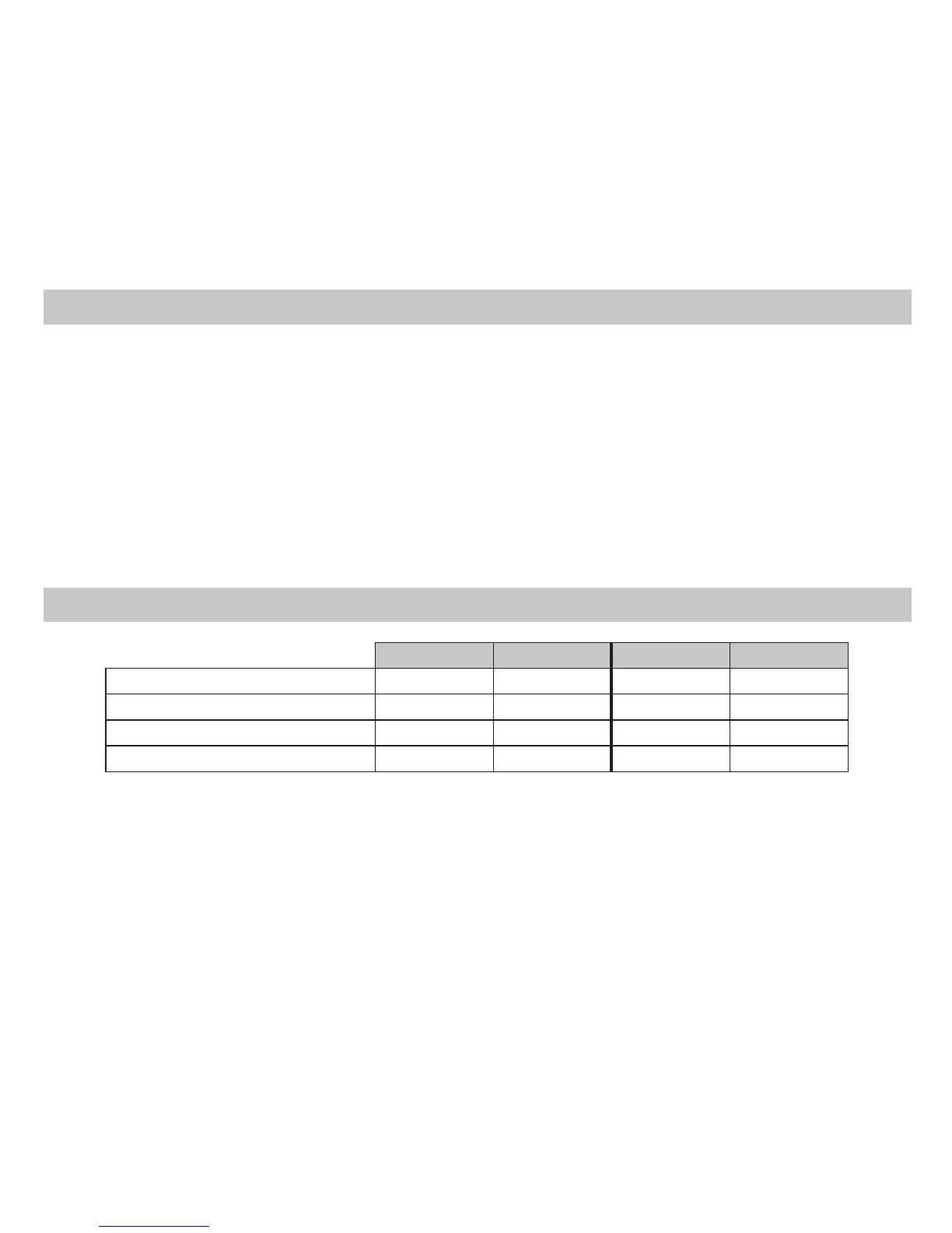
Terminal Designator Descriptions
1
ST
Cool 2
ND
Cool 1
ST
Heat 2
ND
Heat
Heat/Cool Y1,G YI,Y2,G W1,G* W1,W2,G*
Heat Pump (One Compressor) Y1,G,O Y1,G,O Y1,G,B Y1,W2,G,B
Heat Pump (Two Compressors) Y1,G,O Y1,Y2,G,O Y1,G,B Y1,Y2,G,B
Emergency Heat (Heat Pump Only) N/A N/A W2,G W2,G
* G not energized when configured as a gas/oil system
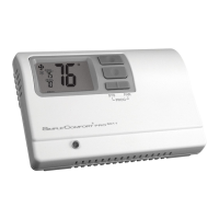
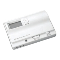
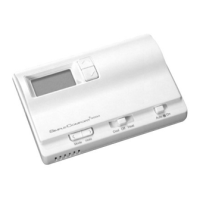
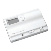
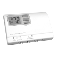
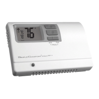
The SC5811 thermostat is configurable for all systems. The configuration directly affects the outputs.
Use the output chart to correctly configure and wire the thermostat to your system.
SC5811 Output Chart
 Loading...