iv
New2001
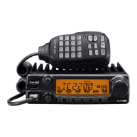
TABLE OF CONTENTSSUPPLIED ACCESSORIES
Mounting bracket
For the mounting bracket
Knob bolts Flat washers (M5)
Screws (5×20 mm) Spring washers (M5)
Microphone
Microphone hanger
and screws (3×16 mm)
Sponges Accessory connectors
6 pin 8 pin
DC power cable (OPC-891A)*
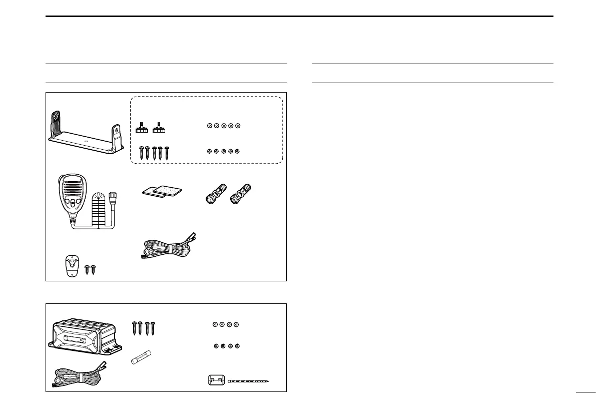
The following items are sold by the set with the GM600.
Spring washers (M5)
Screws (5×20 mm) Flat washers (M5)
DC power cable
(OPC-2352)
PS-310
Spare fuse (FGB 15 A)
Ferrite EMI lter
+ Tie wrap
IMPORTANT ...................................................................................... i
EXPLICIT DEFINITIONS ................................................................... i
DISPOSAL ......................................................................................... i
IN CASE OF EMERGENCY ............................................................. ii
INSTALLATION NOTE ..................................................................... ii
PRECAUTIONS ................................................................................iii
SUPPLIED ACCESSORIES ............................................................ iv
1 OPERATING RULES .................................................................. 1
2 PANEL DESCRIPTION ........................................................... 2–5
■ Front panel .............................................................................. 2
■ Function display (Main screen) ............................................... 3
■ Software key function ..............................................................5
■ Speaker Microphone ............................................................... 5
3 PREPARATION ...........................................................................6
■ Entering the MMSI code .........................................................6
4 BASIC OPERATION ............................................................. 7–12
■ Transmitting and receiving ...................................................... 7
■ DSC Task mode ...................................................................... 8
■ Sending a Distress call .........................................................10
■ Sending an Individual call ..................................................... 11
5 MENU SCREEN .................................................................. 13–14
■ Construction .......................................................................... 13
■ Selecting a Menu item ..........................................................14
6 CONNECTIONS .................................................................. 15–17
■ Connections ..........................................................................15
■ Power supply connections ....................................................17
7 SPECIFICATIONS AND OPTIONS ........................................... 18
■ Specications ........................................................................ 18
■ Options ..................................................................................18
8 COUNTRY CODE LIST .............................................................19
* Use for the
operation check.
(12 V DC only)

 Loading...