22
REMOTE CONTROL
Remote control (CI-V) information
D Command formats
• DV Digital code squelch setting
Command: 1B 07
~ 9
~ 9
XX
• DV MY call sign setting
Command: 1F 00
Set your own call sign and note of up to 12
characters�
See “Character’s code of the call sign�”
X X X X X X X X X X X X
9
1
8
∙∙∙∙∙∙∙∙
1 ~ 8: Your own call sign setting (8 characters)
9 ~ : Note setting (4 characters)
• DV TX call signs setting (24 characters)
Command: 1F 01
Set “UR,” “R1,” and “R2” call signs of 8
characters (fixed)�
See “Character’s code of the call sign�”
X X
∙∙∙∙∙∙∙∙
X X X X X X X X X X
∙∙∙∙∙∙∙∙
∙∙∙∙∙∙∙∙
1 ~ 8: UR (Destination) call sign setting
(8 characters)
9 ~ :
R1 (Access/Area repeater) call sign setting
(8 characters)
~ :
R2 (Link/Gateway repeater) call sign setting
(8 characters)
Character’s code of the call sign
Character ASCII code
0 ~ 9 30 ~ 39
A ~ Z 41 ~ 5A
(Space) 20
/ 2F
• DV TX message setting
Command: 1F 02
Set the transmit message of up to 20 characters�
See “Codes for character entries�” (p� 18)
“FF” stops sending or reading messages�
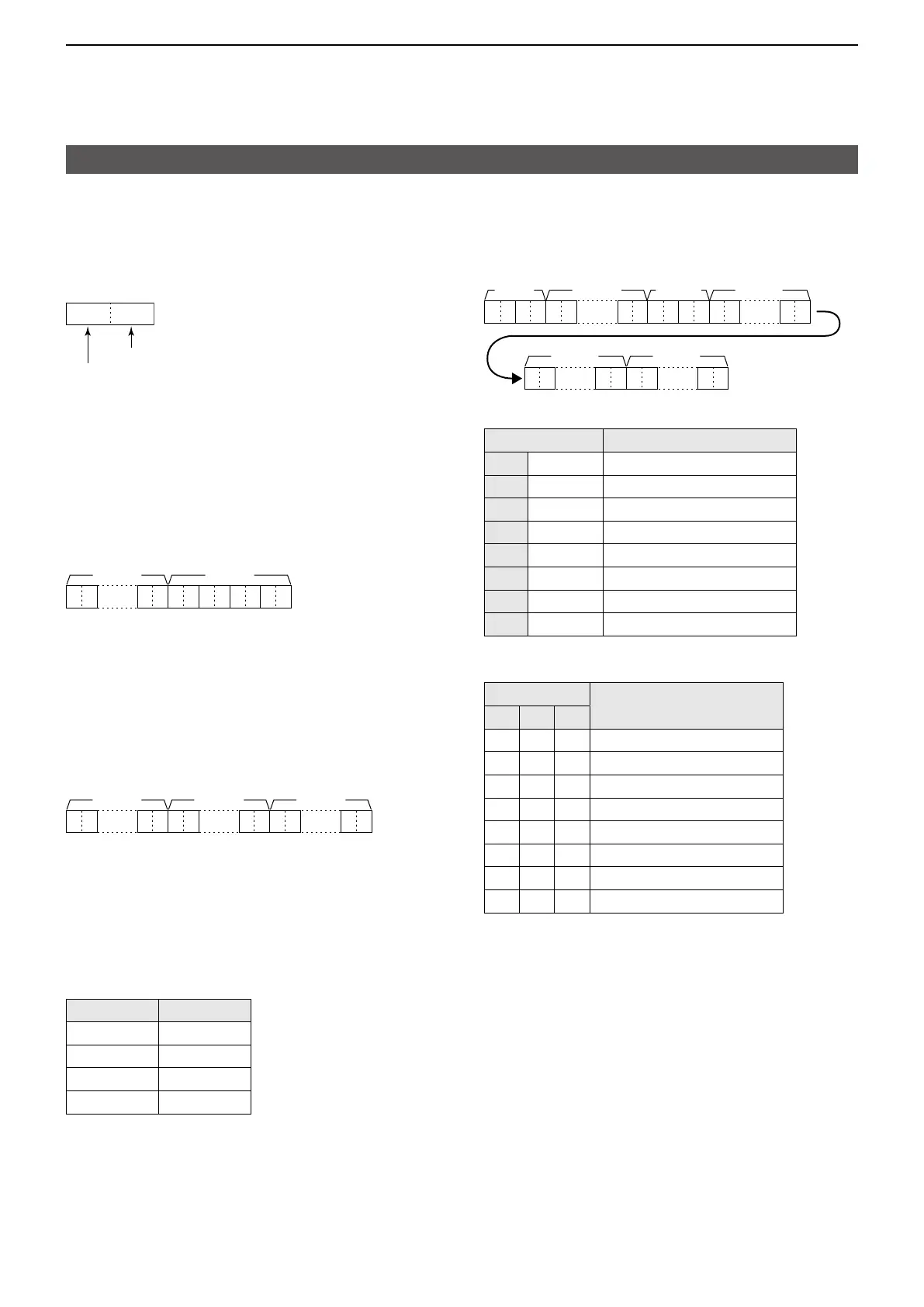
• DV RX call sign data
Command: 20 0001, 0002
X X X X X XXX X X X X
∙∙∙∙∙∙
X XXX
∙∙∙∙∙∙
X X
∙∙∙∙∙∙
X X X X
∙∙∙∙∙∙
X X
~ ~
1: Header flag data (First byte)
Data Description
bit7 (0: Fixed) —
bit6 (0: Fixed) —
bit5 (0: Fixed) —
bit4 0/1 0=Voice, 1=Data
bit3 0/1 0=Direct, 1=Through repeater
bit2 0/1 0=No Break-in, 1=Break-in
bit1 0/1 0=Data, 1=Control
bit0 0/1 0=Normal, 1=EMR
2: Header flag data (Second byte)
Data
Description
bit2 bit1 bit0
1 1 1 Repeater control
1 1 0 Send auto acknowledge
1 0 1 (Not used)
1 0 0 Request to re-transmit
0 1 1 Send acknowledge
0 1 0 Receive no reply
0 0 1 Repeater disabled
0 0 0 NULL
3 ~ : Call sign of the caller station
(8 characters, fixed)
~ : Note of the caller station
(4 characters, fixed)
~ : Call sign of the called station
(8 characters, fixed)
~ :
Call sign of the access/area repeater (R1)
(8 characters, fixed)
~ :
Call sign of the link/gateway repeater (R2)
(8 characters, fixed)
See “Codes for character entries�” (p� 18)
LFF: When no call sign is received since the
transceiver power was turned ON�