26
REMOTE CONTROL
Remote control (CI-V) information
D Command formats
• Selected or unselected VFO frequency settings
Command: 25
X X X X X X X X X X X X
Operating frequency
00=Selected VFO
01=Unselected VFO
See “Operating frequency�” (p� 16)
LWhen using the DR function, the transceiver returns
“FA” (NG) because these cannot be set to 01�
• When VFO A is selected
00=frequency of VFO A changes
01=frequency of VFO B changes
• When VFO B is selected
00=frequency of VFO B changes
01=frequency of VFO A changes
• Selected or unselected VFO’s operating
mode and filter settings
Command: 26
Both data and filter settings can be skipped�
In that case, “DATA OFF” and the default filter
setting of the operating mode is automatically
selected�
1Operating mode setting
3
Filter setting
00=Selected VFO
01=Unselected VFO
XX X X XX XX
LWhen using the DR function, the transceiver returns
“FA” (NG) because these cannot be set to 01�
• When VFO A is selected
00 = operating mode of VFO A changes
01 = operating mode of VFO B changes
• When VFO B is selected
00 = operating mode of VFO B changes
01 = operating mode of VFO A changes
1 Operating mode
setting
2 Data mode
setting
3 Filter
setting
00:LSB 05:FM 00: Data mode OFF 01:FIL1
01:USB 06:WFM 01: Data mode ON 02:FIL2
02:AM 07:CW-R — 03:FIL3
03:CW 08:RTTY-R — —
04:RTTY 17:DV — —
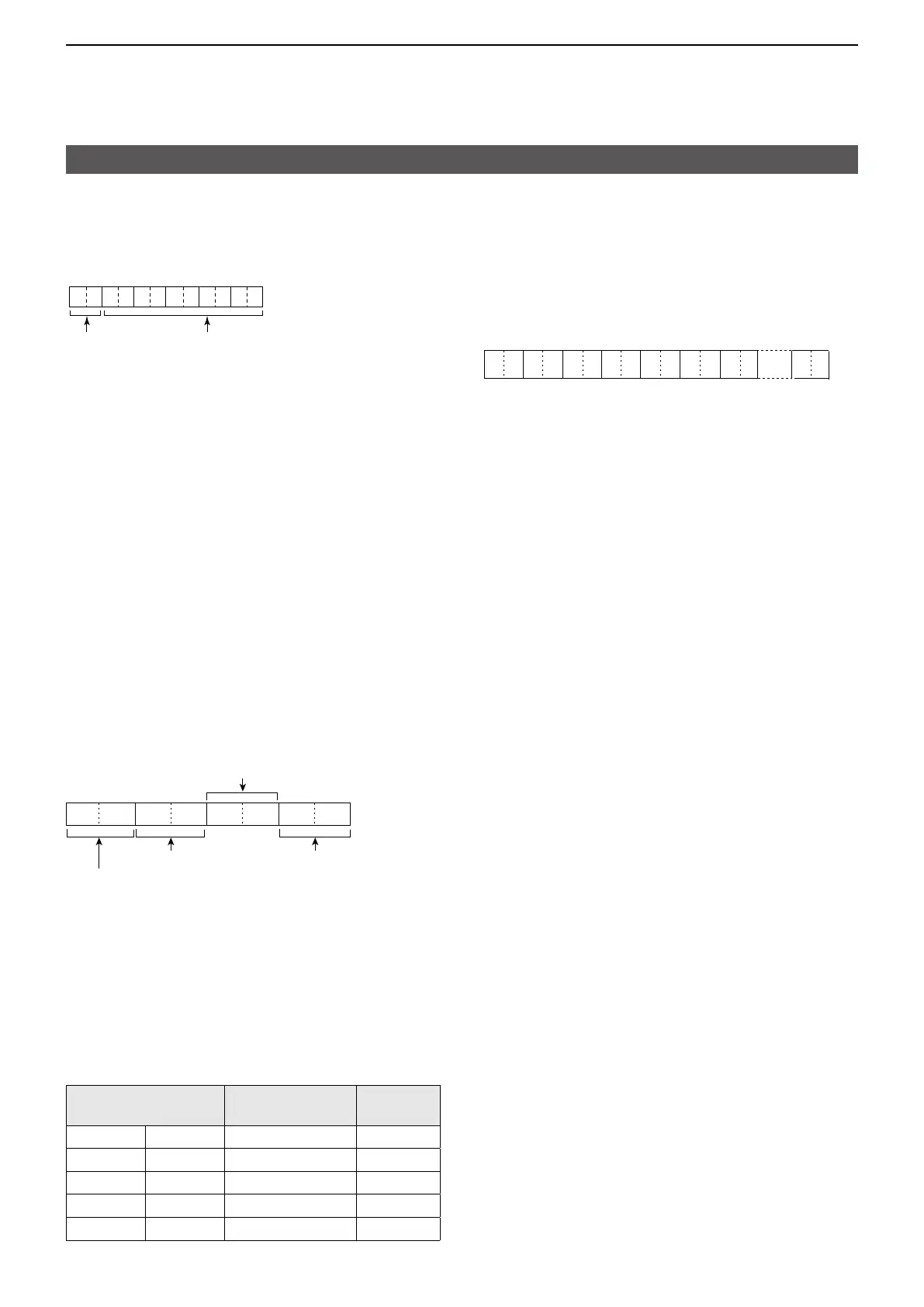
• Scope waveform data
Command: 27 00
Outputs the waveform data to the controller�
X XX X0 0 X XX XX X X X
������
X X
1 2 3 4 5 6 7
1: 00 (Fixed)
2 Order of division data (Current): 01~11
3
Division number (Maximum): 01(WLAN), 11(USB)
LWhen data is sent to the controller using
the WLAN function, all data is sent together�
However, when the data is sent through the
[microUSB] port, the data is divided by 11 and
sent in sequential order�
LThe 1st data sends only the wave information
(1 ~ 6) without the waveform data (7)� The
2nd or later data sends the minimum wave
information (1 ~ 3) with waveform data (7)�
4 Center or Fixed mode data:
• 00 = Center mode scope
• 01 = Fixed mode scope
5 Waveform information:
The waveform information is different between
the Center mode and the Fixed mode�
• In the Center mode:
Center frequency and span are sent�
See page 16 for Operating frequency data,
and the Scope span settings to the right�
• In the Fixed mode:
Lower edge and higher edge frequencies are
sent See page 27 for Scope Fixed edge
frequency settings 3 ~ �
6 Out of range information:
• 00 = In range
• 01 = Out of range
LIf the scope data is out of range, the waveform
data (7) is omitted�
7 Waveform data:
The transceiver outputs the drawn waveform
data� The data range or data length of the
waveform data is judged by the controller�
(The data range is basically the same as the
display size of the scope on the controller�)
• Data range: 0 ~ 160
• Data length: 475