5 - 6
TRANSMITTER ADJUSTMENTS—continued
CARRIER
SUPPRESSION
AM
CARRIER
AM
MODULATION
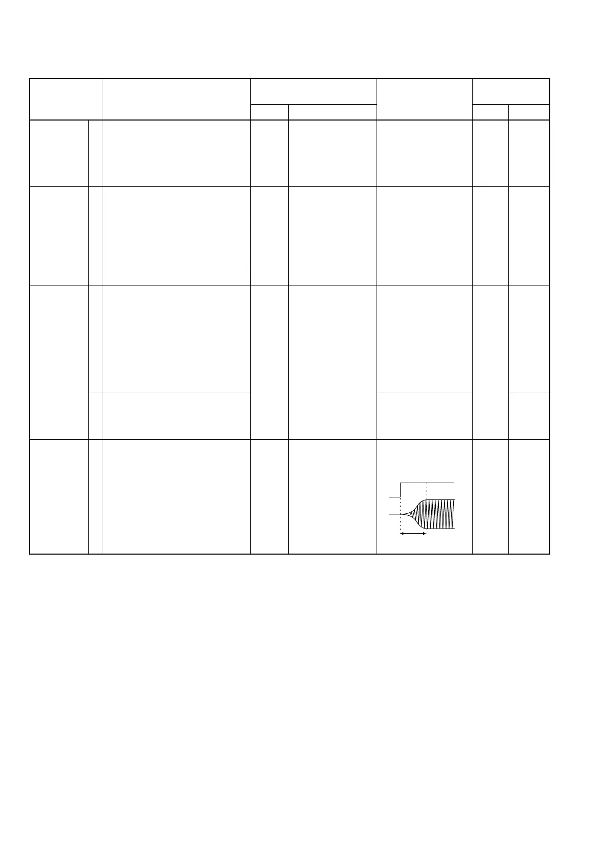
CW
CARRIER
ADJUSTMENT
ADJUSTMENT ADJUSTMENT CONDITION
MEASUREMENT
VALUE
POINT
UNIT LOCATION UNIT ADJUST
1
1
1
2
1
• Display frequency: 14.10000 MHz
• Mode : USB
• Mic gain : Minimum (0)
• Apply no audio signals to [MIC]
connector.
• Transmitting
• Display frequency: 14.10000 MHz
• Mode : AM
• RF power : Maximum (H)
• Mic gain : Minimum (0)
•
R2321 (MAIN unit)
: Center
•
R2385 (MAIN unit)
: Center
• Apply no audio signals to [MIC]
connector.
• Transmitting
• Display frequency: 14.10000 MHz
• Mode : AM
• RF power : Maximum (H)
• Mic gain : Center (50)
•
R2385 (MAIN unit)
: 9 o’clock
• Connect an audio generator to
[MIC] connector and set as:
Frequency : 1 kHz
Level : 3 mVrms
• Transmitting
• Set an AG as:
Frequency : 1 kHz
Level : 30 mVrms
• Transmitting
• Display frequency: 14.10000 MHz
• Mode : CW
• RF power : Maximum (H)
• Connect a keyer to the [KEY] jack.
• Key down (transmitting)
Rear
panel
Rear
panel
Rear
panel
MAIN
Connect a spectrum
analyzer to the [ANT]
connector through an
attenuator.
Connect an RF
power meter to [ANT]
connector.
Connect a modula-
tion analyzer to the
[ANT] connector
through an attenua-
tor.
Connect an oscillo-
scope to CP3701 and
[ANT] connector.
Minimum carrier level
40 W
70% modulation
90% modulation
Adjust as follows:
MAIN
MAIN
MAIN
MAIN
R2303
R1730
R2321
R2385
R3703

 Loading...


