4-1-4 2ND IF AND DEMODULATOR CIRCUITS
(MAIN UNIT)
The 2nd mixer circuit converts the 1st IF signal into a 2nd IF
signal. A double superheterodyne system (which converts
receive signals twice) improves the image rejection ratio
and obtains stable receiver gain.
The FM IF IC (IC6 for channel 70, IC1 for other channels)
contains the 2nd local oscillator, 2nd mixer, limiter amplifier,
quadrature detector, and noise detector circuits, etc.
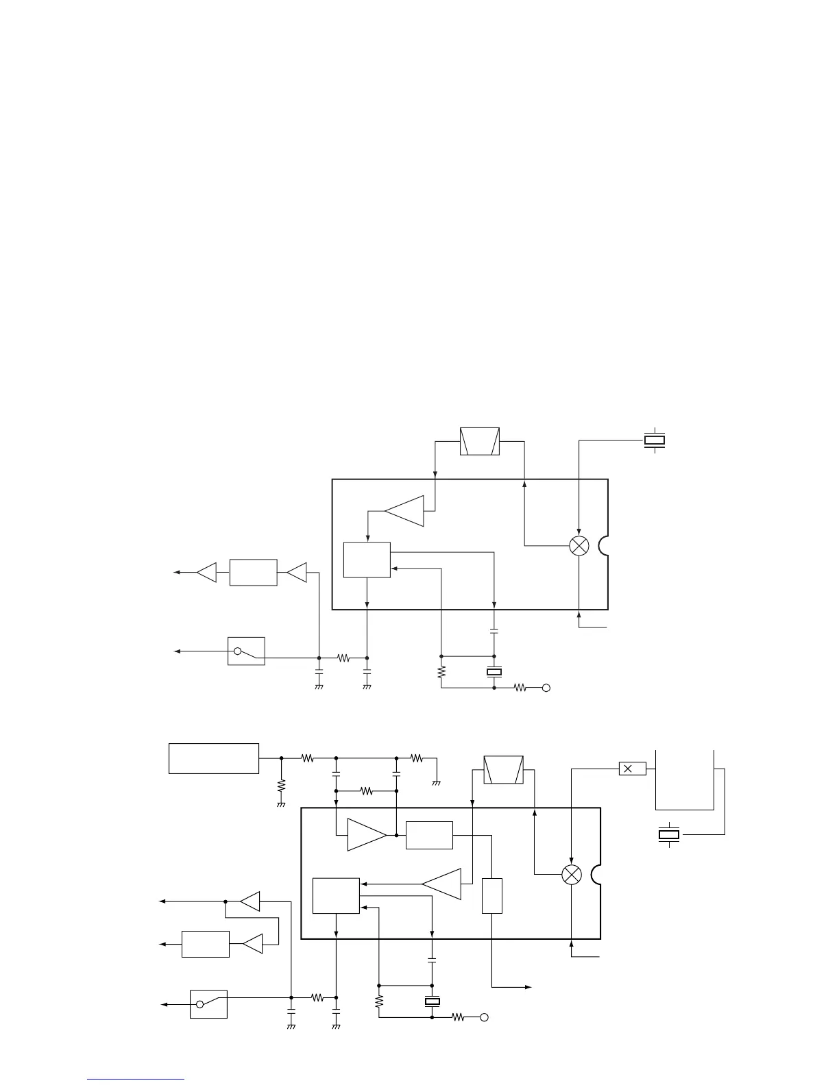
• CHANNEL 70 CIRCUIT
The 1st IF signal from the 2nd IF amplifier (Q10) is applied
to the 2nd mixer section of FM IF IC (IC6, pin 16), and is
mixed with a 21.25 MHz 2nd LO signal, which is generated
at the 2nd oscillator section in IC6 and X3, to produce a 450
kHz 2nd IF signal.
The 2nd IF signal from IC6 (pin 3) is passed through the
ceramic filter (FI6), which unwanted signals are suppressed,
and is then applied to the 2nd IF (limiter) amplifier in IC6 (pin
5). The signal is applied to the FM detector section in IC6
for demodulating into AF signals.
“DEC2” signal
AF signal “DET”
IC5a,
IC5b
IC11
1
910
5
FI6
Limiter
amp.
FM
detector
2nd
mixer
11
X2
8V
3
16
1st IF (21.7 MHz) from Q10
X3
21.25 MHz
2nd IF filter
450 kHz
IC6 TA31136FNG
2
6
IC3c,
IC3d
IC9
DSC
decoder
• 2ND IF AND DEMODULATOR CIRCUITS
(For CHANNEL 70 ONLY)
2nd
Mixer
16
Limiter
amp.
2nd IF filter
450 kHz
PLL IC
IC12
X4
15.3 MHz
X1
(30.6 MHz)
Q16
RSSI
IC1 TA31136FNG
14
1st IF (30.15 MHz) from Q2
"NOISE" signal to the SQL amplifier (IC2, pin 1)
11109
1
7
IC11
IC3a
IC3b
"DEC1" signal
"WXDEC" signal
87 5 3
AF signal "DET"
8V
D/A convertor IC
(IC15, pin 23)
2
17
16
Active
filter
FI3
Noise
detector
FM
detector
2
DSC
decoder
• 2ND IF AND DEMODULATOR CIRCUITS
(For OTHER CHANNELS)
The FM detector circuit employs a quadrature detection
method (linear phase detection), which uses a ceramic dis-
criminator (X2) for phase delay to obtain a non-adjusting
circuit. The detected signal from IC6 (pin 9) is applied to the
AF circuit.
• OTHER CHANNELS CIRCUIT
The 1st IF signal from the 2nd IF amplifier (Q2) is applied
to the 2nd mixer section of FM IF IC (IC1, pin 16), and is
mixed with a 30.6 MHz 2nd LO signal, which is generated
at the PLL circuit using the reference frequency (15.3 MHz),
to produce a 450 kHz 2nd IF signal.
The 2nd IF signal from IC1 (pin 3) is passed through the
ceramic filter (FI3), which unwanted signals are suppressed,
and is then applied to the 2nd IF (limiter) amplifier in IC1 (pin
5). The signal is applied to the FM detector section in IC1
for demodulating into AF signals.
The FM detector circuit employs a quadrature detection
method (linear phase detection), which uses a ceramic dis-
criminator (X1) for phase delay to obtain a non-adjusting
circuit. The detected signal from IC1 (pin 9) is applied to the
AF circuit.
4 - 2