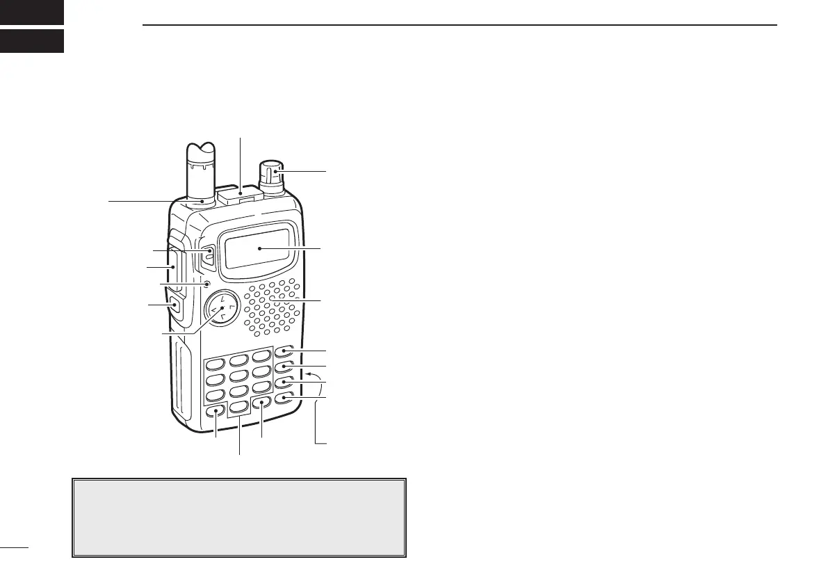
PANEL DESCRIPTION
2
2
q [MULTI]
w [SQL]
e [TX/RX]
r [PTT]
t [PWR]
y
u [SP/MIC]
i [DIAL]
o [VFO]
!0 [MR]
!1 [CALL]
!2 [H/L]
!3 [RIT] !6 [DC13.5V]!5 [M]
!4
Function
display
Speaker/
Microphone
q MULTIFUNCTION SWITCH [MULTI]
➥ Push to select the tone or duplex menu. (pgs. 15–17);
push for 1 sec. to enter set mode (p. 35).
➥ Push ↕ to increase/decrease the volume (p. 11).
➥ Push ↔ to change the operating band; push for 1 sec.
to start a scan (p. 22).
w SQUELCH SWITCH [SQL] (p. 11)
➥ Push and hold to open the squelch.
➥ While pushing, rotate [DIAL] to adjust the squelch set-
ting.
e TX/RX INDICATOR (p. 11)
Lights red while transmitting; green while receiving (or
when the squelch is open).
r PTT SWITCH [PTT] (p. 11)
Push and hold to transmit; release to receive.
t POWER SWITCH [PWR] (p. 9)
Push for 1 sec. to turn power on and off.
y ANTENNA CONNECTOR (p. 1)
Connects the supplied antenna.
u EXTERNAL SPEAKER AND MICROPHONE JACKS
[SP/MIC]
Connect an optional speaker-microphone or headset, if de-
sired. The internal microphone and speaker will not func-
tion when either is connected. (See p. 33 for options.)
■ Switches, controls, keys and connectors
NOTE: In this manual—
Push [MULTI] means push
ñ directly;
Push [MULTI(
↕)] means push ñ up or down; and
Push [MULTI(↔)] means push ñ left or right. See q
IC-T81A/E Manual-(1) 01.12.5 6:55 PM Page 2 (1,1)