5
2
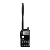
PANEL DESCRIPTION
q FREQUENCY INDICATION
Shows the selected frequency, set mode contents, etc.
w MODE INDICATORS
Indicate the operating mode.
e DUPLEX INDICATOR (p. 15)
Appears during semi-duplex operation.
•“–DUP” appears for minus duplex; “DUP” appears for plus du-
plex.
r TONE INDICATORS
“T” appears when the subaudible tone encoder (p. 15) is in
use; “T SQL
S” appears during pocket beep operation
(p. 26) and “T SQL” appears when the tone squelch func-
tion (p. 25) is activated.
t SKIP INDICATOR (p. 23)
Appears when the selected channel is set as a “skip” chan-
nel.
y MEMORY MODE INDICATOR (p. 11)
Appears while in memory mode.
u MEMORY CHANNEL INDICATOR
Indicates the selected memory channel and other items
such as the call channel, set mode items, etc.
i S/RF INDICATORS (p. 11)
Show the relative signal strength while receiving and the
output power selection while transmitting.
o RIT/VXO INDICATOR (p. 13)
Appears when either the RIT or VXO function is activated
and the 1.2 GHz band is selected.
!0 LOW POWER INDICATOR (p. 11)
Appears when low output power is set.
!1 VOLUME INDICATOR
Appears while adjusting the volume.
• Indicators also appear in place of the operating frequency while
adjusting volume to visually indicate the selected volume level.
IC-T81A/E Manual-(1) 01.12.5 6:55 PM Page 5 (1,1)