EasyManuals Logo
Home>Icom>Transceiver>IC-V8

Icom IC-V8 Service Manual

Icom IC-V8
31 pages
To Next Page IconTo Next Page
To Previous Page IconTo Previous Page
Page #6 background imageLoading...
Page #6 background image
3- 1
SECTION 3 DISASSEMBLY INSTRUCTIONS
3-1 DISASSEMBLY INSTRUCTION
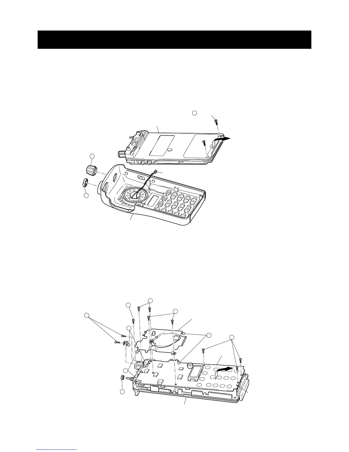
REMOVING THE CHASSIS PANEL
1 Unscrew 1 nut A, and remove 1 knob B.
2 Unscrew 2 screws C.
3 Take off the chassis in the direction of the arrow.
4 Unplug J6 to separate front panel and chassis.
REMOVING THE MAIN UNIT
1
2
Unsolder 3 points D, and unscrew 1 nut E.
3
Unscrew 2 screws F, 2 screws H, and 6 screws G (silver, 2 mm) to separate the chassis and the MAIN unit.
(black, 2 mm) x 2
Front panel
Chassis
J6 (Speaker connector)
B
C
A
H
(black, 2 mm) x 2
(silver, 2 mm) x 6
Shield cover
Guide holes
MAIN unit
Chassis
D
D
G
D
E
G
G
F
(black, 2 mm) x 2
Take off the MAIN unit in the direction of the arrow.

Other manuals for Icom IC-V8

Questions and Answers:

Question and Answer IconNeed help?

Do you have a question about the Icom IC-V8 and is the answer not in the manual?

Icom IC-V8 Specifications

General IconGeneral
BrandIcom
ModelIC-V8
CategoryTransceiver
LanguageEnglish

Related product manuals