26
INTERNAL WIRING
The Logic Combi boiler comes pre-tted with 1.8m of mains cable. This
must be connected to a permanent live supply and NOT switched by
thermostats/programmers. For installers wishing to change this cable
refer to Frame 35.
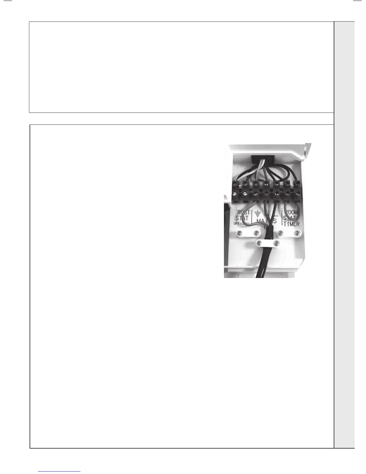
The Logic Combi boiler comes pre-tted with a link wire between the
room thermostat/Timer connections on the terminal strip. This creates
a permanent call for heat and must be removed when adding a room
thermostat/programmer.
To add thermostat/programmer:
1. Isolate the mains supply to the boiler.
2. Remove the front panel. Refer to Frame 37.
3. Swing the control box down into the servicing position. Refer to Frame
50.
4. Route incoming cables through the grommets in bottom panel (note,
grommets are ‘blind’ and will require puncturing) and secure using
clamps and screws provided in hardware pack.
5. Connect wires to terminal block, see instructions opposite.
6. Swing the control box back up into the operating condition and re-t
the front panel ensuring a good seal is made.
Ideal offer 4 kits as follows:
(see individual kits for installation instructions)
Mechanical Timer (24 hr) Kit - 24 hour mechanical CH
timer ts into the control box of the boiler. This can be tted
in conjunction with a room thermostat.
Electronic Timer (7 day) kit - 7 day electronic CH timer
ts into the control box of the boiler. This can be tted
in conjunction with a room thermostat. Features English
language installation help messages.
RF Mechanical Programmable Room Thermostat (24
hr) kit - Combined 24 hour mechanical timer and room
thermostat with wireless communication to receiver unit
which ts into control box of the boiler.
RF Electronic Programmable Room Thermostat (7
day) kit - Combined 7 day timer and room thermostat
with wireless communication to receiver unit which ts
into control box of the boiler. Features English language
installation help messages. Also OpenTherm Control for
gas consumption saving.
ROOM THERMOSTAT (NO TIMER) - WIRING
1. Remove link wire between Room stat/timer terminals.
2. Connect room stat across terminals as shown in diagram A -
see Frame 27.
3. If room stat has a neutral connection, connect this to terminal
N (load) in the fused spur.
ROOM THERMOSTAT + TIMER - WIRING
1. Remove link wire between Room stat/timer terminals.
2. Connect room stat and programmer in series as shown in
diagram B - see Frame 27.
3. If room stat has a neutral connection, connect this to terminal
N (load) in the fused spur.
FROST THERMOSTAT - WIRING
If parts of the system are vulnerable to freezing or the
programmer is likely to be left off during cold weather, a frost stat
should be tted in conjunction with a pipe thermostat.
1. Position the frost thermostat in a suitable position, i.e. area
vulnerable to freezing.
2. Connect frost stat across terminals marked frost stat as
shown in diagrams A and B - see Frame 27.
25
ELECTRICAL CONNECTIONS
Wiring should be 3 core PVC insulated cable, not less than
0.75mm
2
(24 x 0.2mm), and to BS 6500 Table 16. For IE
reference should be made to the current ETCI rules for
electrical installations.
Connection must be made in a way that allows complete
isolation of the electrical supply such as a double pole switch
having a 3mm (1/8”) contact separation in both poles. The
means of isolation must be accessible to the user after
installation.
WARNING. This appliance MUST be earthed.
A mains supply of 230Vac ~ 50 Hz is required.
The fuse rating should be 3A. All external controls and wiring
must be suitable for mains voltage.
Wiring external to the boiler MUST be in accordance with the
current I.E.E. (BS.7671) Wiring Regulations and any local
regulations.
INSTALLATION