6
1. Refer to Frame 43.
2. Drain down the boiler. Refer to Frame 57.
3. Unplug the electrical lead.
4. Unscrew the thermistor (to facilitate removal a
13mm socket spanner should be used).
5. Fit the new thermistor using the sealing
washer provided.
6. Reassemble in the reverse order.
7. Rell the boiler. Refer to Frame 24.
8. Check the operation of the boiler. Refer to
Frames 32 & 33.
67
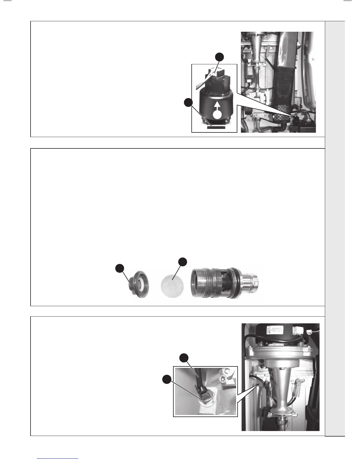
FLOW THERMISTOR REPLACEMENT
4
3
5
5
65
CH WATER PRESSURE SENSOR REPLACEMENT
1. Refer to Frame 43.
2. Drain the boiler. Refer to Frame 57.
3. Remove condensate trap/siphon. Refer to Frame 53.
4. Using a suitable tool pull out the retaining clip.
5. Pull the pressure sensor upwards to remove.
6. Unplug the electrical connection and transfer to the new
pressure sensor.
7. Push the new pressure sensor onto the rear pump housing
and t retaining clip.
8. Reassemble in reverse order.
9. Rell the boiler. Refer to Frame 24.
10. Check Operation of the boiler. Refer to Frames 32 & 33.
6
4
66
DHW FILTER & DHW FLOW REGULATOR CLEANING / REPLACEMENT
1. Refer to Frame 43.
2. Isolate the mains cold water supply to the boiler.
3. Drain the boiler DHW circuit. Refer to Frame 57.
4. Remove the DHW ow turbine cartridge. Refer to Frame 61.
5. Unscrew the ow regulator housing.
6. Remove the lter.
7. Clean or replace lter as necessary.
8. Reassemble in reverse order.
9. Rell the boiler. Refer to Frame 24.
10. Check Operation of the boiler. Refer to Frames 32 & 33.
1. Refer to Frame 43.
2. Isolate the mains cold water supply to the boiler.
3. Drain the boiler DHW circuit. Refer to Frame 57.
4.
Remove the DHW ow turbine cartridge. Refer to Frame 61.
5. Unscrew the ow regulator housing.
6. Inspect the ow regulator for any blockage and remove if
necessary.
7. Reassemble in reverse order.
8. Rell the boiler. Refer to Frame 24.
9. Check Operation of the boiler. Refer to Frames 32 & 33.
SERVICING