WARNING. Whilst effecting the required gas tightness test and purging air from the gas installation,
open all windows and doors, extinguish naked lights and DO NOT SMOKE.
A. Electrical Installation
1. Checks to ensure electrical safety should be carried out by
a competent person.
2. ALWAYS carry out the preliminary electrical system
checks, i.e. earth continuity, polarity, resistance to earth
and short circuit, using a suitable test meter.
3. After wiring the boiler, all grommets in the bottom panel
MUST be in place to ensure that the boiler case sealing is
maintained.
B. Gas Installation
1. The whole of the gas installation, including the meter,
should be inspected and tested for tightness and purged in
accordance with the recommendations of BS. 6891.
In IE refer to IS.813:2002.
2. Purge air from the gas installation by the approved methods
only.
31
COMMISSIONING AND TESTING
GENERAL
Please Note: The combustion for this appliance has
been checked, adjusted and preset at the factory for
operation on the gas type dened on the appliance
data plate. DO NOT adjust the air/gas ratio valve.
Having checked:
- That the boiler has been installed in accordance
with these instructions.
- The integrity of the ue system and the ue seals,
as described in the Flue Installation section.
Proceed to put the boiler into operation as follows:
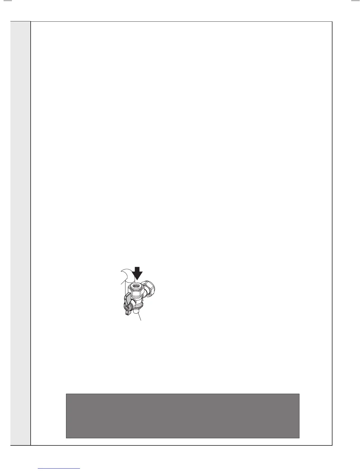
CHECK THE OPERATIONAL (WORKING) GAS
INLET PRESSURE
Set up the boiler to operate at maximum rate by
opening hot tap to maximum ow.
With the boiler operating in
the maximum rate condition
check that the operational
(working) gas pressure at
the inlet gas pressure test
point complies with the
requirements - refer to “Gas
Supply” on page 8.
Ensure that this inlet pressure
can be obtained with all other
gas appliances in the property
working.