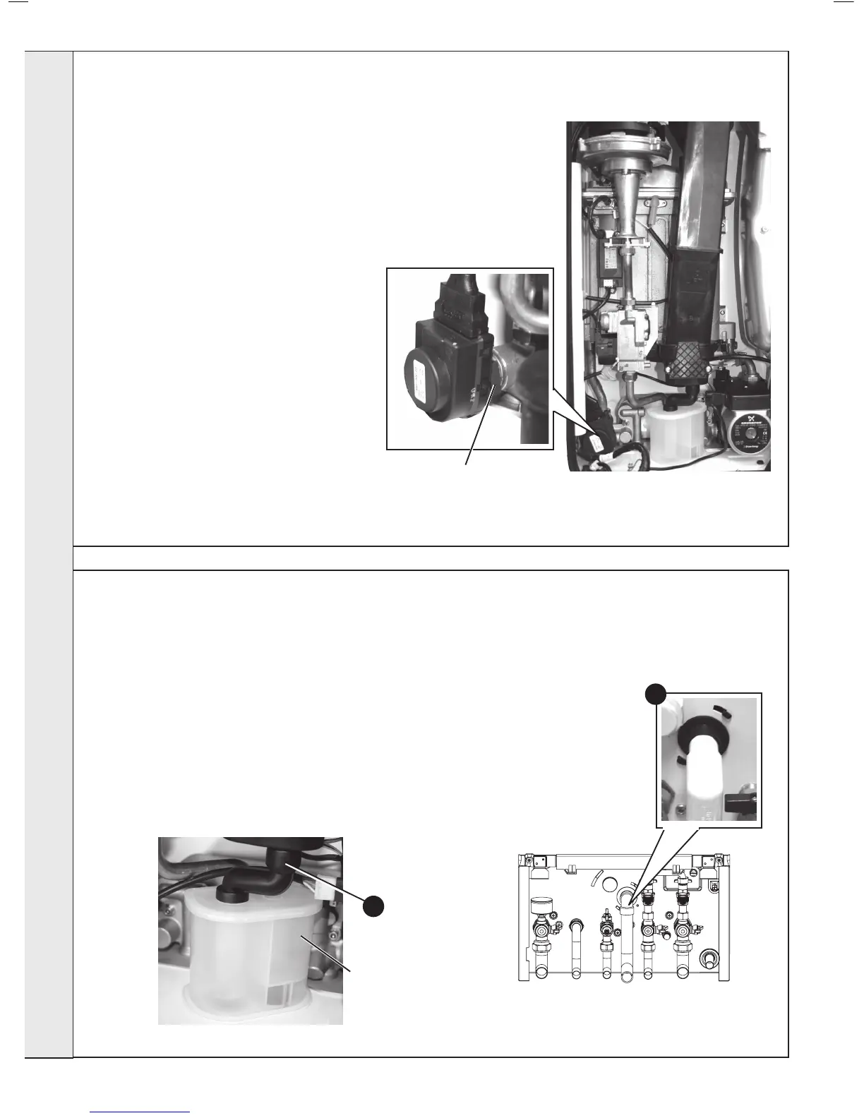
1. Refer to Frame 43.
2. Pull off the rubber pipe at the sump drain.
3. Disconnect the condensate drain pipe.
4. Turn the siphon clockwise to disengage and lift to remove.
Note. Keep siphon upright when removing
5. Clean siphon with water.
6. Re-assemble in reverse order.
7. When re-assembling ensure the trap is full of water.
8. Check operation of the boiler. Refer to Frames 32 & 33.
53
CONDENSATE TRAP/SIPHON REPLACEMENT
3
2
Siphon
52
DIVERTER VALVE ACTUATOR REPLACEMENT
1. Refer to Frame 43.
2. Remove the electrical plug.
3. Using a suitable tool pull out the retaining
clip and lift the diverter head from the brass
body.
4. Fit new actuator head and reassemble in
reverse order.
6. Check operation of the boiler. Refer to
Frames 32 & 33.
Diverter Valve Actuator
Retaining Clip
SERVICING