73
TILT-A-WAY
HYDRAULIC OPERATOR
PROPORTIONAL VALVE DRIVER SETTINGS
The Lynch Electronics Digital Display Proportional Valve Driver has been set at Ideal Mfg., Inc. and should not need any adjustments.
If for some reason the settings need to be checked, or reset the following are the Ideal Mfg., Inc. suggested settings.
SET-UP (see page 61 drawing # HYJG-236)
1. Turn the power off (ref # 1), remove the red wire on the motor control board from the Solenoid Valve output terminal for the
direction needing adjustment (ref # 2) (open solenoid / close solenoid). Only adjust one Solenoid Valve Driver at a time.
2. Connect the red wire removed from the motor control board to the 24 Volt DC terminal on the motor control board (ref # 3).
3. Turn the power on (ref # 1). Locate the Solenoid Valve Drive that power is being supplied to (ref # 4). Remove screw that holds
the Solenoid Valve Drive to the Proportional Valve Coil. Unplug the Solenoid Valve drive from the coil, pull straight out.
4. At power up, the display will show either the output current signal or the input signal (Default display setting shows the output
signal).
5. Rotate SELECT to enter the set-up mode.
6. When you reach the setting you want to modify, rotate ADJUST up or down to the desired value.
7. To modify another setting, rotate SELECT again and repeat.
8. The Driver is fully functional during the set-up procedure with any adjustments effective immediately.
9. In order to write the new settings in the memory and return to normal mode of operation, rotate SELECT until the display shows
SA, and then rotate ADJUST or wait for 100 seconds.
10. If you do not want to save the new settings you have just modified, you must disconnect the Driver from the power supply before
the end of the 100 seconds to restore the previous settings.
11. After saving parameters to memory, the decimal point will be flashing and the Driver display will be back showing either the
output current signal or input signal depending on your di selection.
12. To start over completely, you can restore the Lynch factory settings by rotating SELECT to rFP and then rotate ADJUST up past
10 for the display to reset. (NOTE for Step 9: You may have to adjust your Input Signal Setting Again if you reset to factory
settings.)
13. When settings are set turn power off, install Solenoid Valve Driver on coil, and secure with screw removed. Disconnect red wire
for 24 Volt DC terminal, and return it back to the terminal on the motor control board. Repeat for the other Solenoid Valve
Driver is needed. Be sure to remove jumper wire if used before turning power back on.
14. Turn power on and operate the gate to check if adjustments are acceptable. Repeat if needed.
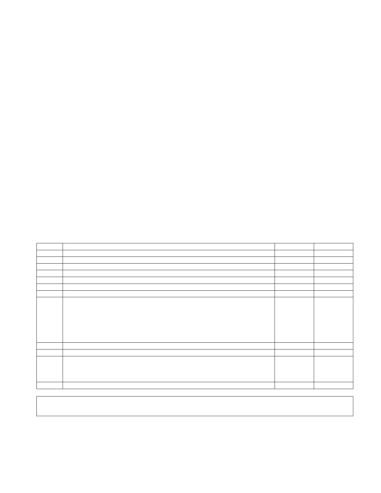
Display Description Close setting Open setting
Hi: HIGH, Maximum Current Output. (Amps) do not set above 1.6 1.6 1.6
Lo: LOW, Minimum Current Output. (Amps) (See: NOTE 1) 0.64 0.70
rUP: RAMP UP, Time for Output to increase from min to max. (Sec) 0.2 0.2
rDN: RAMP DOWN, Time for Output to decrease from max to min. (Sec) 1.0 1.1
Cdb: COMMAND DEADBAND, Output disabled if command signal less than dead band. (%) 0 0
dFr: DITHER FREQUENCY, (Hz) 180 180
in: INPUT SIGNAL SELECTION, 5 (0 to 5V) or 10 (0 to 10V) or 420 (4 to 20mA) 5 5
di: DISPLAYED SIGNAL FOR TROUBLESHOOTING, 0 (command signal in [volts] or
[milliamps]) or 1 (solenoid current in [amps])
**Flashing decimal point is an indicator for present display mode**
-Fast Flashing decimal point, several flashes per second indicates di: = 0
-Slow Flashing decimal point, 1 per second indicates di: = 1
-No Flashing decimal point or No decimal point indicates display in SETTING/ADJUST
mode
1 1
SA: SAVE SETTINGS
rfP: RESET FACTORY PARAMETERS (See: NOTE 2)
Err: ERROR DETECTION STATE, Short Circuit, Reverse polarity protection and detection
Error 0 – No Errors
Error 1 – Overcurrent in driver likely due to short circuit in Solenoid
Error 2 – Current exceeding 20 mA in “4 to 20 mA” input mode
Clr: CLEAR ERROR, clears Driver of Error State (See: NOTE 2)
When adjusting the HI and LO parameters, note the HI parameter value cannot be adjusted below the LO parameter value as
well the LO parameter value cannot exceed the HI parameter value.
NOTE 2: Adjust Parameter Value up past 9 to operate this command setting.
 Loading...