offset = 0.0
slope = 1.0
r correlation coefficient = 1.0
c % of variability = 100%
The operator can now confirm or modify the offset and slope coefficients.
Offset = 0.0 Slope = 1.0
The Turbidity meter sensor calibration proceeds as above with the calibration of the remaining
measuring scales :
Measuring scale 2, Full scale [500 FTUl]
Measuring scale 3, Full scale [125FTU]
Measuring scale 4, Full scale [25 FTU]
After the last coefficients have been confirmed, the operator must choose the measuring scale that the
probe sets up after the wake-up. During data acquisition, the turbidity meter measuring scale is
automatically selected by the probe management firmware to be the most sensitive one.
Turbidity meter scale:(1)>750 FTU,(2)500 FTU,(3)125 FTU,(4)25 FTU
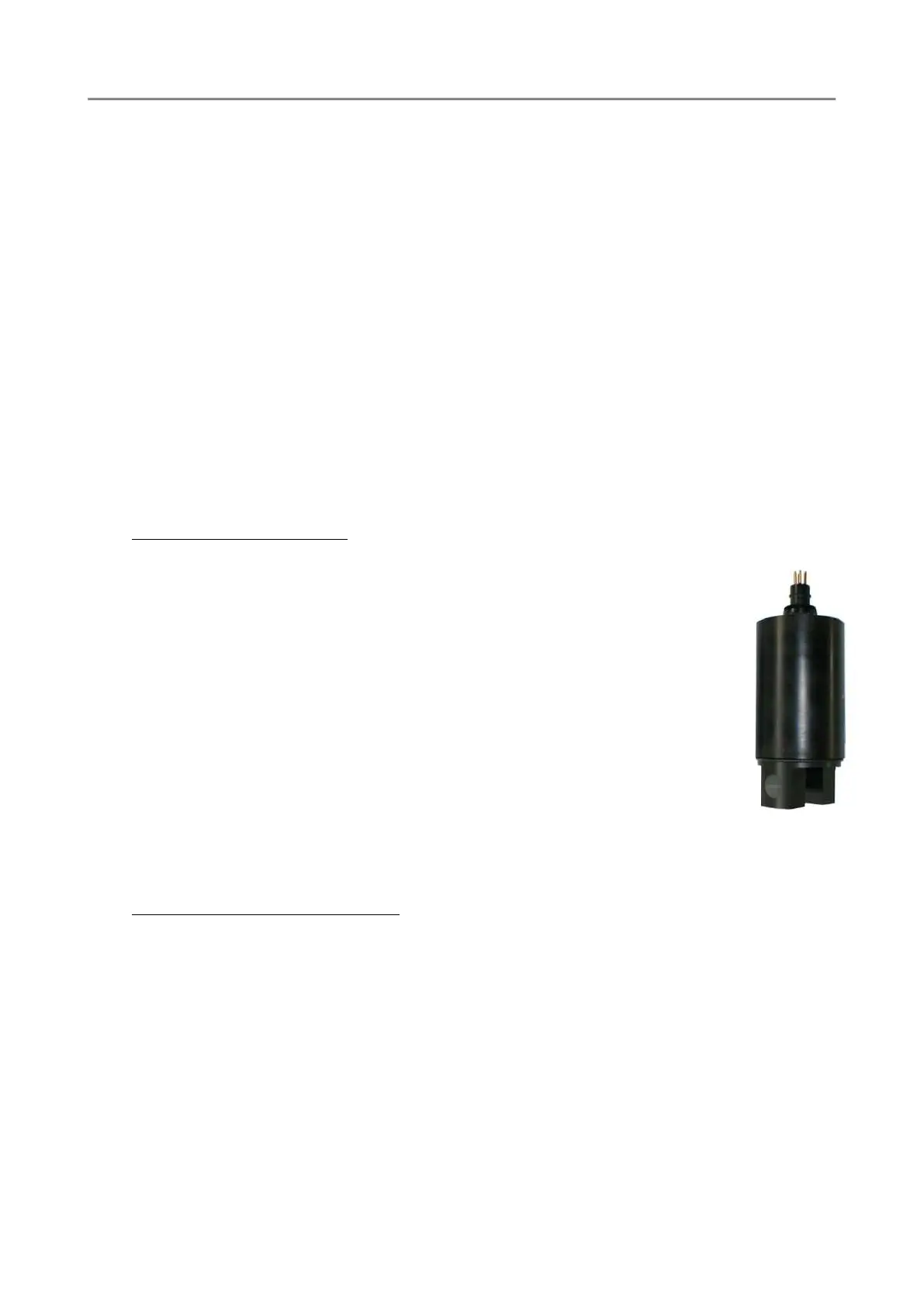
5.6.2 SEAPOINT OEM Fluorometer
The SEAPOINT Fluorometer allows the user to monitor chlorophyll concentration by
directly measuring the amount of fluorescence emission from a given sample of water.
The sample media is pumped through a quartz tube mounted through the long axis of
the instrument. Chlorophyll, when excited by the presence of an external light source,
absorbs light in certain regions of the visible spectrum and re-emits a small portion of
this light as fluorescence at longer wavelengths. SEAPOINT uses two bright blue LEDs
(centred at 455 nm and modulated at 1 kHz) to provide the excitation. Blue interference
filters are used to reject the small amount of red light emitted by the LEDs. A detector,
positioned at 90
o
to the axis of the LED mounts, measures the emitted light from the
sample volume. The approximately 0.25 cm3 sample volume is defined by the
intersection of the excitation light with the field of view of the detector, within the
quartz flow tube. A red interference filter is used to discriminate against the scattered
blue excitation light. The red fluorescence emitted at 90
o
is synchronously detected at
1 kHz by a silicon photodiode. The amplified and demodulated voltage output of the
photodiode is provided to the user for connection to a digital voltmeter or an a-d
converter.
The calibration procedure is the same described for the turbidity meter. The only differences are the
measuring scales, which in the case of the fluorometer are: 5, 15, 50 and 160 µg/l.
5.6.3 WETLabs - C-STAR Transmissometer
The C-Star Transmissometer measures light transmittance at a single wavelength over a known path.
The instrument is configured at the time of purchase to have a path length of 25 or 10 cm and
wavelengths of either 370, 470, 530, or 660 nm. In general, losses of light propagating through water can
be attributed to two primary causes: scattering and absorption. By projecting a collimated beam of light
through the water and placing a focused receiver at a known distance away, one can quantify these
losses. The ratio of light gathered by the receiver to the amount originating at the source is known as
the beam transmittance (Tr). This is the fundamental measurement performed by the C-Star. Suspended
particles, phytoplankton, bacteria and dissolved organic matter all contribute to the losses sensed by
the instrument. They, combined with the intrinsic optical properties of the water itself, govern the
radiative transfer properties within the earth’s natural waters. Thus, the information provided by the
C-Star provides both an indication of the total concentrations of matter in the water as well as a value
of the water clarity. The beam attenuation coefficient is an absolute term to represent these losses. For
a given wavelength, transmittance is related to the beam attenuation coefficient by the following
transfer equation.