DM-F Series Monitor
Page 30
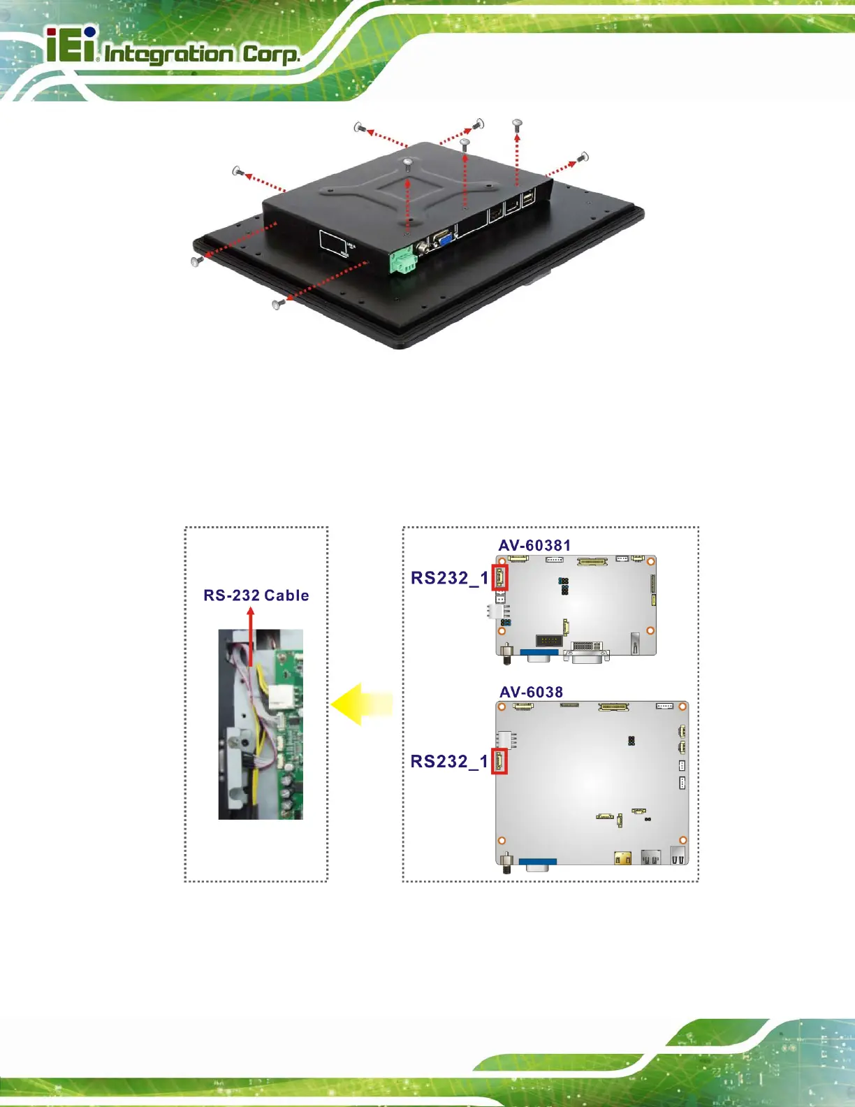
Figure 3-10: Rear Panel Retention Screw Removal (12”–24”)
Step 2: Remove the RS-232 knockout hole on the side panel.
Step 3: Connect the RS-232 flat cable to the internal RS-232 connector (1x9 pin,
RS232_1) on the AD board. See Figure 3-11.
Figure 3-11: Connecting RS-232 Cable
Step 4: Insert the D-sub 9 connector of the RS-232 flat cable into the hole and secure
the connector with two hex jack screws.
 Loading...